Setup
Setting Up the RS232C Interface
Connector pinout
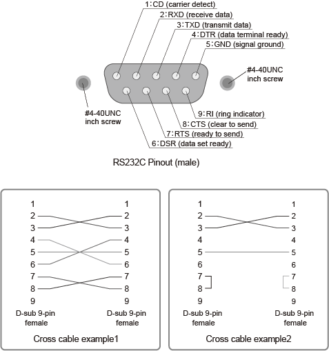
For the RS232C cable, use a D-sub, 9-pin, female-to-female AT cross cable. The figure below shows the port pinout.

If you are not using flow control, you do not have to connect all the pins. (See the second crossover cable wiring example below.)
9-pin AT connector (Flow control cannot be performed using the cable described in the second crossover cable wiring example.)
Connection Procedure
Turn off the POWER switches of the PLZ12005WH/PLZ20005WH and computer.
Using an RS232C cable, connect the PLZ12005WH/PLZ20005WH to the PC.
Setting Procedure
1. Press SYSTEM and then Configure Interface on the front panel.
If the Interface screen does not appear, press Configure Interface again.
2. Configure the protocol (the baud rate, data length, stop bits, and flow control) by selecting the respective Bitrate, Data Bits, Stop Bits, and Flow Ctrol items under RS232C Adjustment.
For the settings, see the table under Protocol below.
3. Turn the POWER switch of the PLZ12005WH/PLZ20005WH off and on again to enable the settings.
Protocol
The RS232C protocol is shown in the following table. The underlined values are the factory default settings.
| Item | Value |
|---|---|
| Bitrate | 9 600 bps/ 19 200 bps/ 38 400 bps/ 57 600 bps/ 115 200 bps |
| Data Bits | 8 bits (fixed) |
| Stop Bits | 1 bit (fixed) |
| Flow Ctrol | NONE/ CTS-RTS |
Break signal
The break signal is used as a substitute for the IEEE488.1 dcl/sdc (Device Clear, Selected Device Clear) message.
NOTE
| If you are going to use remote control, we recommend that you set the PLZ12005WH/PLZ20005WH in remote mode (set SYST:COMM:RLST to REMote or RWLock). When operating in remote mode, REMOTE appears on the front panel display. |