Tutorial
Triggering Output Change (SEQuence1:TRANsient)
PCR-M/PCR-LE/PCR-LE2 has five different trigger subsystems -TRANsient, SYNChronize, ACQuire, SIMulation, and PROGram. These features are mapped to SEQuence1 to SEQuence5 respectively, as the SCPI specification generally categorizes each trigger subsystem as a numbered Trigger Sequence.
The TRANsient (SEQuence1) group is a trigger subsystem that changes the output voltage and frequency settings.
State
The three states are available in the sequence operation. -> See for details
Output Change Control
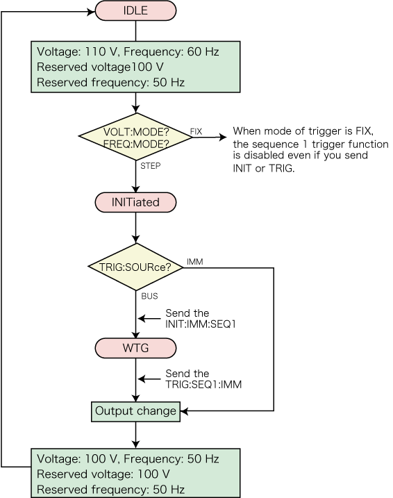
Using TRIGger:SEQuence1 (or TRIGger:TRANsient) subsystem allows you to synchronize the output changes with a given trigger. This is convenient if you want to synchronize output changes with other instrument actions such as external DC power supply or electronic loads.
To reserve triggered settings, use the VOLTage:TRIGgered and FREQuency:TRIGgered commands. Keep in mind that the MODE settings for each output item must be set to STEP prior to using triggers.
:VOLTage 110 'Sets the voltage to 110 V
:FREQuency 60 'Sets the frequency to 60 Hz
:VOLTage:MODE STEP 'Sets the voltage trigger mode to STEP
:FREQuency:MODE STEP 'Sets the frequency trigger mode to STEP
:VOLTage:TRIGgered 100 'Sets the voltage that will be set when a trigger is received to 100 V
:FREQuency:TRIGgered 50 'Sets the frequency that will be set when a trigger is received to 50 Hz
:TRIGger:SEQuence1:SOURce BUS 'Sets the trigger source to BUS
:INITiate 'Initiates sequence 1 (starts the trigger function)
:TRIGger 'Applies a software trigger to sequence 1
If you repeatedly change the output, a trigger error (-210) may occur. By using the *OPC command, you can prevent this error. ->see for detail
:TRIGger;*OPC 'Apply a trigger and wait until the output change is complete.

The TRIGger:SEQuence1:SOURce command sets the trigger source to BUS or IMMediate.
When the Trigger Source is set to IMMediate, the change is executed immediately causing the voltage and/or frequency to change to a new setting. When the Trigger Source is set to BUS, the trigger subsystem goes to the WTG (Waiting For Trigger) state. When a software trigger is applied with the TRIGger:SEQuence1:IMMediate or *TRG command, the change is executed.
When the operation is completed, the trigger subsystem returns to the IDLE state again. When an ABORt or an equivalent command is sent without executing the trigger, the change is cancelled, and then the trigger subsystem returns to the IDLE state.
Setting items that are programmable in the sequence 1 group are VOLTage, VOLTage:OFFSet, and FREQuency. CURRent limit settings are not associated with the trigger subsystem.
By *RST and *RCL default, VOLTage:MODE, FREQuency:MODE, and VOLTage:OFFSet:MODE are all reset to FIXed. This means that the sequence 1 trigger function is disabled. The MODE settings must be explicitly set to STEP for each output item.
The TRIGger:SEQuence1:IMMediate command applies a software trigger to the sequence 1 group
You can also use the *TRG command or the IEEE488.1 get (Group Execute Trigger) command for the same purpose. This command applies a software trigger to all the sequence groups, so if there are other sequence groups that are in the INITiated state, their sequences will also be executed at the same time.
On the PCR-M, you do not have to send an initiate command for every trigger. You can configure sequences so that they continue automatically.
INITiate:CONTinuous:SEQuence1 ON
Operation using a software trigger
When ABOR is sent, INIT:SEQ1 is cancelled. The VOLT:TRIG setting does not change.
Table below shows the responses when the voltage is set to 20 V (VOLT 20) and when the target value to which the voltage is to change using a trigger is set to 10 V (VOLT:TRIG 10).
| Response | ||
|---|---|---|
| VOLT? | VOLT:TRIG? | |
| Immediately after the setting | 20 V | 10 V |
| After a trigger is sent | 10 V | 10 V |
| After *RST is sent | 0 V | 0 V |
| Voltage change VOLT 30 is sent before sending a trigger | 30 V | 30 V(cancel) |