Interface Setup
Interface Setup for PCR-LEPCR-LE2 series
RS232C (standard equipped)
RS232C connection
Turn off the POWER switch on the PCR-LEPCR-LE2 and the computer.
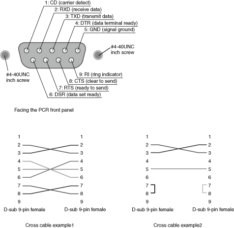
Use a D-sub 9-pin female-to-female AT type crossover cable for the RS232C cable. Figure shows the connector pin assignments.
If you are not using flow control, you do not have to connect all the pins. (See the second crossover cable wiring example below.)

9-pin AT type connector (Flow control cannot be performed using the cable described in the second crossover cable wiring example.)
RS232C configuration
1. Press CONFIG (SHIFT+OPR MODE), COM-I/F, TYPE, and then RS232C.
2. Then, configure the protocol (the baud rate, data length, stop bits, and flow control settings).
For the settings, see the table under Protocol below.
3. Restart the PCR-LEPCR-LE2.
The settings are applied.
Protocol
The following table shows the settings that correspond to the RS232C protocol.
Underlined values are factory default settings.
| Item | Setting | Baudrate |
9 600 bps/ 19 200 bps/ 38 400 bps |
|---|---|
| Data | 8 bit / 7 bit |
| Stop | 1 bit / 2 bit |
| Parity | Fixed to none |
| Flow Ctrl | OFF/ RTS・CTS |
RS232C communication
Use flow control for RS232C communication.
| Hard flow | Function |
|---|---|
| RTS | Request to send |
| CTS | Clear to send |
Break signal
The break signal functions as a substitute for the IEEE488.1 dcl / sdc (Device Clear, Selected Device Clear) message.
NOTE
| The RS232C interface should be shifted remotely by the command. Use the "SYSTem:REMote" SCPI command to set the RS232C interface to the remote state. Be sure to include this command at the start of the program when you are performing remote programming. |