AC power supply PCR-LE series
Appendix
Analog signal Interface boards (EX05-PCR-LE, EX06-PCR-LE)
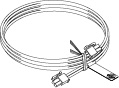
Control Panel Extension Cable (EC05-PCR)
Line Impedance Network (LIN3060J, LIN1020JF, LIN3020JF)
Sequence creation and control software (SD011-PCR-LE)
RMT CONT SOFTWARE FOR PCR-LE
(SD021-PCR-LE)
Immunity Tester (DSI1020, DSI3020, SD009-PCR-LE)
Single-phase three-wire output, Three-phase output (optional)
Master-slave parallel operation
Power-sync cable (LC01-PCR-LE)
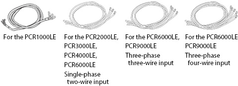
These are power cords for the PCR-LE Series. The switchboard ends of the power cords have not been prepared for connection. The power cords do not conform to IEC standard.
|
|
Model |
Cable |
Length |
Nominal cross sectional area |
Input terminal |
|
PCR1000LE |
AC5.5-3P3M-M4C |
Heavy PVC jacketed three-core cable |
3 m |
5.5 mm2 |
M4 |
|
PCR2000LE |
AC8-1P3M-M5C-3S |
Three single-core cables |
3 m |
8 mm2 |
M5 |
|
PCR3000LE PCR6000LE Single-phase, two-wire input |
AC14-1P3M-M8C-3S |
Three single-core cables |
3 m |
14 mm2 |
M8 |
|
PCR4000LE |
AC22-1P3M-M8C-3S |
Three single-core cables |
3 m |
22 mm2 |
M8 |
|
PCR9000LE Three-phse, three-wire input |
AC14-1P3M-M5C-4S |
Four single-core cables |
3 m |
14 mm2 |
M5 |
|
PCR9000LE Three-phase, four-wire input |
AC5.5-1P3M-M5C-5S |
Five single-core cables |
3 m |
5.5 mm2 |
M5 |
By using the rack mount brackets, you can mount the PCR500LE, PCR1000LE, and PCR2000LE to the KRO1600, KRO1250, KRO900, and KRC Series standard racks made by Kikusui.
The following table lists the brackets that are used to attach the PCR-LE Series to EIA inch racks or JIS millimeter racks. For details on how to mount the product to the rack, see the each operation manual.
|
|
Type of rack to mount to |
Bracket model |
|
PCR500LE |
EIA inch rack |
KRB4 |
|
JIS millimeter rack |
KRB200 |
|
|
PCR1000LE |
EIA inch rack |
KRB6 |
|
JIS millimeter rack |
KRB300 |
|
|
PCR2000LE |
EIA inch rack |
KRB9 |
|
JIS millimeter rack |
KRB400-PCR-LE |
Detach the casters before you mount the PCR-LE Series to a rack mount frame.
Detaching the feet and casters
We recommend that you keep all pieces that you have removed from the PCR-LE Series. You will need these pieces if you remove the PCR-LE Series from the rack.
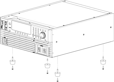
Detaching the feet (PCR500LE)
Remove the screw that hold each foot in place to detach the four feet.
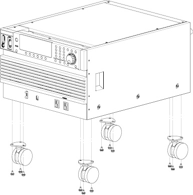
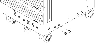
Detaching the casters (on models other than the PCR500LE)
Remove the three screws that hold each caster in place to detach the four casters.
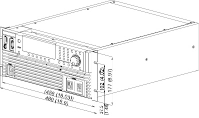
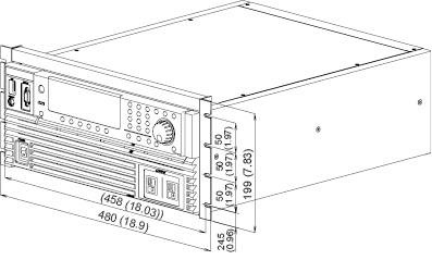
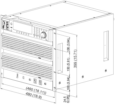
Outline diagram and dimensions
Unit: mm (inch)
• PCR500LE
When mounting on an inch rack (bracket model KRB4)
When mounting on a millimeter rack (bracket model KRB200)
• PCR1000LE
When mounting on an inch rack (bracket model KRB6)
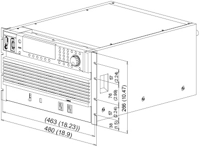
When mounting on a millimeter rack (bracket model KRB300)
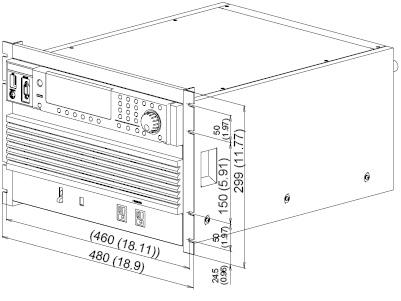
• PCR2000LE
When mounting on an inch rack (bracket model KRB9)
When mounting on a millimeter rack (bracket model KRB400-PCR-LE)
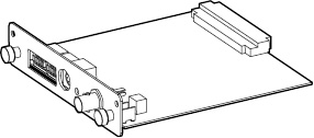
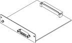
By using one of the interface boards listed below, you can use an interface other than RS232C to control the PCR-LE Series.
US05-PCR-LE: This board enables you to control the PCR-LE Series over USB.
IB05-PCR-LE: This board enables you to control the PCR-LE Series over GPIB.
LN05-PCR-LE: This board enables you to control the PCR-LE Series over a LAN.
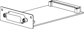
(The figure here is an example of the IB05-PCR-LE.)
Insert the interface board in SLOT 4 on the rear panel.
Installing
Do not handle the interface board in environments where static electricity is easily produced.
|
1 |
Check that the POWER switch is off. |
|
2 |
Touch a grounded metal object (for example, the metal parts of the rear panel) to discharge any static electricity from your body. |
|
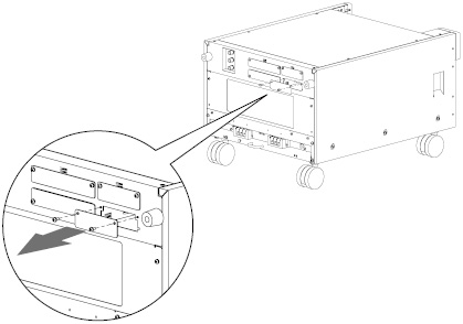
3 |
Remove the screws that are holding the SLOT 4 cover in place on the rear panel, and remove the cover from the panel.
|
|
4 |
Hold the panel parts of the board so that the printed circuit board side is facing up. |
|
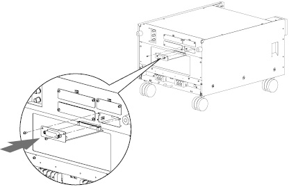
5 |
Insert the board into the slot so that the printed circuit board's connector is inserted into the connector at the back of the slot.
|
|
6 |
Insert the board all the way into the slot. |
|
7 |
Use the screws that you removed in step 3 to fix the board in place in the panel. |
|
8 |
If you installed the LAN interface board (LN05-PCR-LE), to change the host name, use the Web interface. The factory default host name is “PCR-LE.” To access several PCR-LEs using host names, you need to change the host name. For details on the Web interface, see “Interface Setup” in the Communication Interface Manual. |
|
9 |
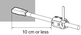
If you have installed the USB interface board (US05-PCR-LE), attach the ferrite core and the cable tie. A ferrite core (96-01-0210) and cable tie (P4-000-551) are included with the USB interface US05-PCR-LE. Attach the ferrite core at a position 10 cm or less from the USB port. Check that the ferrite core is locked securely in place. Attach the cable tie to fix the position of the ferrite core.
|
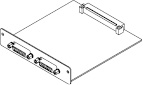
Analog signal Interface boards (EX05-PCR-LE, EX06-PCR-LE)
By using one of the analog signal interface boards listed below, you can control PCR-LE Series AC power supply output with analog signals.
• EX05-PCR-LE simply amplifies the waveforms that it receives and outputs the result.
• EX06-PCR-LE varies the voltage of the output AC waveform (sine wave) on the basis of DC signals that it receives.
Insert the board in SLOT 3 on the rear panel.
For connections, see the EX05-PCR-LE/ EX06-PCR-LE Setup Guides.
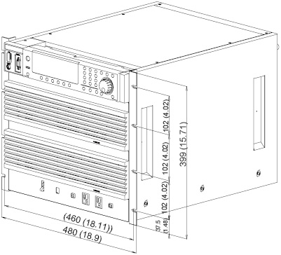
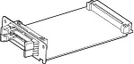
These are used when you want to fix the PCR4000LE, PCR6000LE, or PCR9000LE to a rack or the floor.
For details, see the OP03-KRC section in the OP03-KRC Manual.
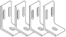
When you are using these with the PCR4000LE, PCR6000LE, or PCR9000LE, you can use a coin or similar object to detach the caps that are included with the PCR-LE Series, then attach the base hold angles. Nuts that are included with the OP03-KRC will not be used.
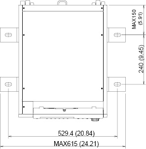
The dimensions of the product when the base hold angles are attached to it are shown in the following figure.
Unit: mm
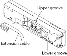
This is an extension cable (2 m in length) that enables you to use the control panel while it is detached from the PCR-LE Series.
|
1 |
Check that the POWER switch is off. |
|
2 |
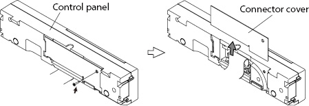
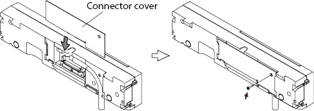
Remove the screw on the back of the control panel that is fixing the connector cover in place. Slide the connector cover up to detach it from the control panel.
|
|
3 |
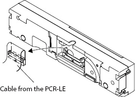
Remove the cable that is connected to the control panel.
|
|
4 |
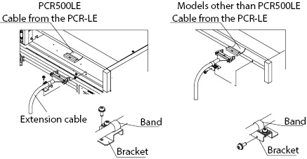
Connect the cable from the PCR-LE Series to the control panel extension cable. Use the band and the bracket to fix the control panel extension cable to the PCR-LE Series. The direction that the bracket is used on the PCR500LE is different from the direction used on all other models.
|
|
5 |
Connect the control panel extension cable to the control panel. Store the cable in the upper or lower groove.
|
|
6 |
Slide the connector cover back onto the control panel. Use the screws that you detached in step 2 to fix the cover in place. The following figures show an example in which the cable is stored in the lower groove.
|
Line Impedance Network (LIN3060J, LIN1020JF, LIN3020JF)
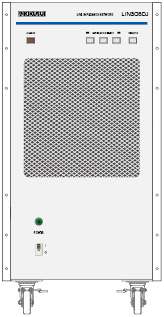
Connecting a standardized line impedance network between the PCR-LE Series and the load enables you to simulate a commercial power supply.
Insert the supplied board in SLOT 3 on the rear panel.
• LIN3060J
This product contains impedances required for testing grid-connected power conditioners as defined in the applicable JIS/JET standards. It is a reference impedance unit necessary for constructing a JETGR0002-1-2.0 grid-interconnection test system.
For details, see the LIN3060J Operation Manual.
• LIN1020JF/ LIN3020JF
This product contains JIS- and IEC-compliant impedances required for harmonic and flicker testing of devices connected to power distribution systems. A test system can be configured easily by combining this product with AC power supplies.
The LIN1020JF can be used to test single-phase devices. When used in combination with the OP01-LIN1020JF, it can be used to test single-phase three-wire devices and three-phase devices.
The LIN3020JF can be used to test single-phase three-wire devices and three-phase devices.
For details, see the LIN1020JF/ LIN3020JF Operation Manual.
Sequence creation and control software (SD011-PCR-LE)
Sequence creation and control software SD011-PCR-LE Wavy for PCR-LE is used to create and execute sequences for PCR-LE series.
For details, see the SD011-PCR-LE Operation Manuals (Setup Guide, Operation Guide).
RMT CONT SOFTWARE FOR PCR-LE
(SD021-PCR-LE)
SD021-PCR-LE is a software application for controlling a Kikusui PCR-LE/PCR-LE2 series AC power supply from a Windows OS tablet PC.
For details, see the SD021-PCR-LE Operation Manual.
Immunity Tester (DSI1020, DSI3020, SD009-PCR-LE)
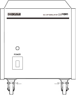
By using the control software (SD009-PCR-LE), the dip simulator (DSI1020/ DSI3020), and the PCF-LE Series, you can perform voltage dip, short interruptions, and voltage variation immunity tests in accordance with IEC61000-4-11 (2004).
The DSI1020 supports single-phase two-wire tests. The DSI3020 supports single-phase two-wire, single-phase three-wire, three-phase three-wire, and three-phase four-wire tests.
Insert the supplied board in SLOT 3 on the rear panel.
For details, see the DSI1020/DSI3020 Operation Manual, and SD009-PCR-LE Setup guide and Operation manual.
Single-phase, three-wire output Three-phase output
• 2P05-PCR-LE
This board enables you to operate the PCR-LE Series in single-phase, three-wire output.
Insert the board in SLOT 1 on the rear panel.
• 3P05-PCR-LE/ 3P05-PCR-LE(500HZ LMT)
These boarsd enables you to operate the PCR-LE Series in three-phase output. 3P05-PCR-LE(500HZ LMT) limits the maximum output frequency of PCR-LE series to 500 Hz.
Insert the board in SLOT 1 on the rear panel.
• CC01-PCR-LE/ CC02-PCR-LE
Cables for single-phase three-wire output boards and three-phase output boards.
The length of the drive-signal cable that comes with the 2P05-PCR-LE/3P05-PCR-LE is 75 cm. 150 cm and 280 cm are available as options.
|
|
Length |
MODEL |
|
Connecting cables |
150 cm |
CC01-PCR-LE |
|
280 cm |
CC02-PCR-LE |
For connections, see the 2P05-PCR-LE and 3P05-PCR-LE/ 3P05-PCR-LE(500HZ LMT) Setup Guides.
• PD05M-PCR-LE/ PD05S-PCR-LE
The PD05M-PCR-LE is used on the master unit. The PD05S-PCR-LE is used on slave units.
Insert the board in SLOT 2 on the rear panel.
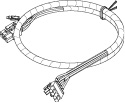
• PC01-PCR-LE
Cable (130 cm) to connect between each bord of parallel operation.
• CC11-PCR-LE
Power signal cable (100 cm) for parallel operation.
For connections, see the PD05M-PCR-LE/ PD05S-PCR-LE Setup Guide.
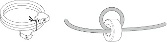
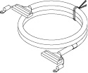
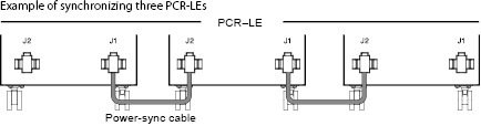
A power-sync cable (1 m in length) enables you to configure the system so that when you turn on a PCR-LE, all the other PCR-LEs also turn on.
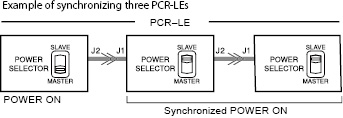
The power signal travels from the J2 connector to the J1 connector. Operating the POWER switch of the PCR-LE whose J1 connector is open will cause the other PCR-LEs to respond in sync.
Power ON
|
1 |
Check that the POWER switch is off. |
|
2 |
Use the power-sync cable to connect the J1 connector and the J2 connector on the PCR-LE rear panels. Do not connect two J1 connectors to each other or two J2 connectors to each other. Insert the cable firmly into the connectors until the are locked in place.
|
|
3 |
Set the POWER SELECTOR switch of the PCR-LE whose J1 connector is open to MASTER. The POWER SELECTOR switch is on the front panel (on the rear panel on the PCR500LE). |
|
4 |
Set the POWER SELECTOR switches of the other PCR-LEs to SLAVE. |
|
5 |
Turn ON the POWER switches of the PCR-LEs whose POWER SELECTOR switches have been set to SLAVE. Even when you turn ON the POWER switches, the PCR-LEs do not turn on. |
|
6 |
Turn ON the POWER switch of the PCR-LE whose POWER SELECTOR switch has been set to MASTER. The PCR-LEs that have been set to SLAVE will also turn on. |
Power OFF
When you turn OFF the POWER switch of the PCR-LE whose POWER SELECTOR switch has been set to MASTER, the PCR-LEs that have been set to SLAVE also turn off.
Power OFF in an Emergency
In an emergency, turn OFF all POWER switches.
To Stop Synchronization
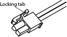
Hold down the locking tab of the power-sync cable, and pull it free of the unit.
Set the POWER SELECTOR switches of all PCR-LEs to “MASTER”.
![]() AC power supply PCR-LE series
AC power supply PCR-LE series
Appendix