AC power supply PCR-LE series
Advanced
Using the Sequence Function (Cont.)
Executing, pausing, and stopping sequences
A sequence is a series of settings—values such as the output voltage, frequency, and time—that are saved in advance and are then recalled and automatically carried out in order at a later time.
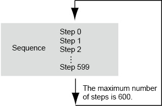
Sequences are groups of executable units called steps. When a sequence is executed (run), its steps are executed in order, starting with the specified starting step. A single execution of a sequence is completed after the sequence’s specified last step has been executed.
You can use the jump function to skip steps and repeatedly execute all the steps in the sequence except for those that have been skipped.
First, set the starting step, and then set the sequence conditions.
If the last step of a sequence does not turn the output off, the output will remain on when the sequence is complete.
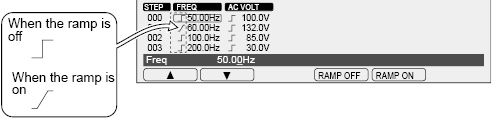
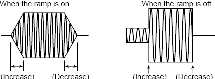
To change the frequency or voltage linearly over the specified time, select “RAMP ON.” To change the value as a step, select “RAMP OFF.”
If you specify “RAMP ON” in step 0, the signal will change linearly from the current voltage or frequency.
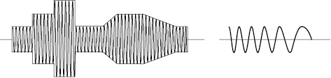
• Signal change of voltage
• Signal change of frequency
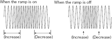
• Signal change of phase
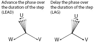
During three-phase output (optional), you can set the phase ramp (leading or lagging). This is effective for varying the line voltage.
Signal output and Resuming
If the status signal is enabled, a status signal will be output while a step is being executed.
If the trigger signal output is enabled, a signal is output for several tens of microseconds when a step is executed.
You can apply a trigger signal to resume a paused sequence.
Starting phase angle and the ending phase angle
Steps are managed in terms of time.
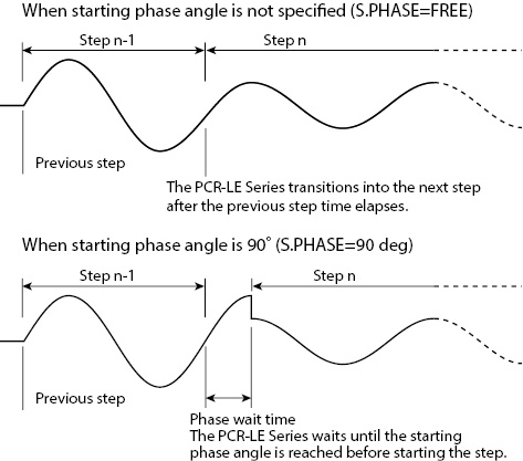
If you set the starting phase angle, steps will start from the specified phase angle.
Phase wait time is the duration from the point when the step time of the last step has elapsed to the point where the phase angle reaches the starting phase angle. The phase wait time is dependent on frequency.
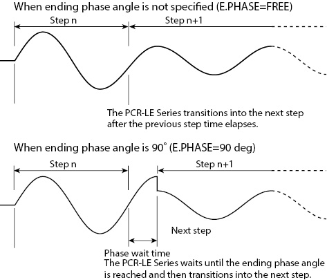
If you set the ending phase angle, the PCR-LE Series will end the step when the specified phase is reached.
Phase wait time is the duration from the point when the step time has elapsed to the point where the phase angle reaches the ending phase angle. The phase wait time is dependent on frequency.
You can output the same waveform regardless of whether you set the starting phase angle or the ending phase angle.
When a waveform is to be output continuously (the phase does not change suddenly) and you set both the starting and ending phase angles, the waveform may be offset by one period. To avoid confusion, we recommend that you set the starting phase angle and not the ending phase angle (FREE).
Display and signal output during the phase wait time
During the phase wait time, the screen shows the next step number. The elapsed time remains at zero until the next step starts.
The status signal is output while the waveform of the step that is enabled is being output.
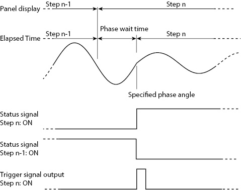
If you set both the starting and ending phase angles and specify phase change, the phase will change suddenly.
If you set sudden phase change to ON, you can switch between two steps according to the set phase angles. For example, if you set the step n-1’s ending phase angle to 90°, the step n’s starting phase angle to 270°, and set sudden phase change to ON, when the step time of step n-1 elapses and 90° is reached, a transition is made to step n (270° phase angle).
Jump function
The steps in a sequence are normally executed in order starting with the starting step. However, you can use the jump feature to skip over steps and repeat sets of steps by repeatedly executing jumps.
Sequence tutorial
Appendix A in the supplied CD-R operation manual contains sequence tutorials that explain sequence creation basics, phase angle settings, sudden phase changes, and multi-phase operation.
These settings cannot be made if you are using the synchronization function.
There are six types of step editing screens (seven types for single-phase, three-wire output and three-phase output (optional)).
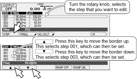
Press SEQ (SHIFT+SIM) and then EDIT (F5) to display the step editing screen.
Items that are common between screens 1/5 to 5/5
A border is displayed around the step or item that you are setting. First use the rotary knob to specify the step that you want to configure, and then configure its settings.
|
Item |
Title |
Description |
|
STEP |
STEP |
Sets the step (0 to 599) that you want to configure |
|
▼ |
-- |
Sets the next step as the one that you want to configure |
|
▲ |
-- |
Sets the previous step as the one that you want to configure |
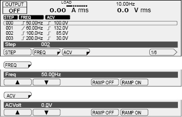
1: Frequency and AC voltage
Use this screen to set the frequency and the AC voltage. The step signal change can also be set for the frequency and the AC voltage.
In AC+DC mode, the step’s AC voltage and output voltage can each be set within their own setting range. If the peak AC+DC output voltage exceeds the PCR-LE Series’ rated output voltage, the output voltage waveform (the peak section) may be distorted (clipped).
During single-phase, three wire output and three-phase output (optional), if you are setting the phases separately, press AC VOLT (F2) to first set all the phases at the same time, and then press ACV V (F4) and ACV W (F5) to set the V phase and W phase, respectively. The AC voltage signal change is shared between all phases.
|
Item |
Title |
Description |
Valid modes |
|
|
FREQ |
Freq |
Sets the step’s frequency (1.00 Hz to 999.9 Hz) |
AC and AC+DC |
|
|
|
RAMP OFF |
Disables the ramped frequency signal change |
||
|
RAMP ON |
Enables the ramped frequency signal change |
|||
|
ACVOLT*1 |
ACVolt AC PhaseVolt*1 |
Sets the step’s AC voltage (0.0 V to 305.0 V) |
||
|
|
RAMP OFF |
Disables the ramped AC voltage signal change |
||
|
RAMP ON |
Enables the ramped AC voltage signal change |
|||
|
ACV V*3 |
AC V PhaseVolt |
Sets the step’s AC voltage (0.0 V to 305.0 V) (V phase) |
AC and AC+DC |
|
|
|
RAMP OFF*4 |
Disables the ramped AC voltage signal change |
||
|
RAMP ON*4 |
Enables the ramped AC voltage signal change |
|||
|
ACV W*5 |
AC W PhaseVolt |
Sets the step’s AC voltage (0.0 V to 305.0 V) (W phase) |
||
|
|
RAMP OFF*4 |
Disables the ramped AC voltage signal change |
||
|
RAMP ON*4 |
Enables the ramped AC voltage signal change |
|||
*1. During single-phase, three-wire output and three-phase output (optional), all phases are set at the same time. Set the voltage using phase voltage.
*2. The display during single-phase, three-wire output and three-phase output (optional)
*3. Single-phase three-wire output or three-phase output (optional) only
*4. This is shared between all phases. You cannot set it for each phase.
*5. Three-phase output (optional) only
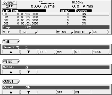
2: Execution time, waveform bank, and output
Use this screen to set the step execution time, the waveform bank, and the output.
|
Item |
Title |
Description |
Valid modes |
|
|
TIME |
HOUR |
Time(HOUR) |
Sets the step time’s hours (0 hours to 1000 hours) |
All |
|
MIN |
Time(MIN) |
Sets the step time’s minutes (0 minutes to 59 minutes) |
||
|
SEC |
Time(SEC) |
Sets the step time’s seconds (0 seconds to 59 seconds) |
||
|
100US |
Time(100us) |
Sets the step time’s microseconds in units of 100 us (0 us to 999900 us) |
||
|
WB NO |
WB No. |
Sets the waveform bank number that you want to use (0 to 63) |
AC and AC+DC |
|
|
OUTPUT |
OFF |
Output |
Turns the output off |
All |
|
ON |
Turns the output on |
|||
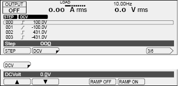
3: DC voltage
Use this screen to set the DC voltage. The step signal change can also be set for the DC voltage.
In AC+DC mode, the step’s AC voltage and output voltage can each be set within their own setting range. If the peak AC+DC output voltage exceeds the PCR-LE Series’ rated output voltage, the output voltage waveform (the peak section) may be distorted (clipped).
If you are setting the voltage of each phase separately for two-phase output or three-phase output (optional), press DCV (F2) to first set all the phases at the same time, and then press DCV V (F4) and DCV W (F5) to set the V phase and W phase, respectively. The DC voltage signal change is the same for all phases.
|
Item |
Title |
Description |
Valid modes |
|
|
DCV*1 |
|
DCVolt DC PhaseVolt*2 |
Sets the step’s DC voltage (0.0 V to ±431.0 V) |
DC and AC+DC |
|
RAMP OFF |
Disables the ramped DC voltage signal change |
|||
|
RAMP ON |
Enables the ramped DC voltage signal change |
|||
|
DCV V*3 |
|
DC V PhaseVolt |
Sets the step’s DC voltage (0.0 V to ±431.0 V) (V phase) |
AC+DC |
|
RAMP OFF*4 |
Disables the ramped DC voltage signal change |
|||
|
RAMP ON*4 |
Enables the ramped DC voltage signal change |
|||
|
DCV W*5 |
|
DC W PhaseVolt |
Sets the step’s DC voltage (0.0 V to ±431.0 V) (W phase) |
|
|
RAMP OFF*4 |
Disables the ramped DC voltage signal change |
|||
|
RAMP ON*4 |
Enables the ramped DC voltage signal change |
|||
*1. --Single-phase, three-wire output (optional)
For DC mode or single-phase, three-wire output in AC+DC mode (2PMODE OFF): Set the U phase voltage (the V phase is automatically set to the same amplitude as the U phase but with opposite polarity).
For two-phase output (2PMODE ON) in AC+DC mode: Set the phase voltage of all phases at once.
--Three-phase output (optional)
Set the phase voltage of all phases at once.
*2. The display during single-phase, three-wire output and three-phase output (optional)
*3. Two-phase output and three-phase output only (optional).
*4. This is shared between all phases. You cannot set it for each phase.
*5. Three-phase output only (optional).
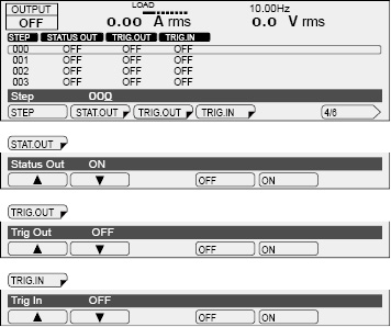
4: Status output, trigger output, and waiting trigger (pause)
 WARNING
Risk of electric shock. Use the BNC connector with an isolation voltage of 63 Vpeak or less.
Use this screen to set the Status output, trigger output, and waiting trigger.
Use the configuration settings to set the signal polarity. -> Status signals
During single-phase, three-wire output or three-phase output (optional), apply signals to and output signals from the U-phase unit.
|
Item |
Title |
Description |
|
|
STAT.OUT |
OFF |
Status Out |
Turns status output off |
|
ON |
Turns status output on |
||
|
TRIG.OUT |
OFF |
Trig Out |
Turns trigger output off |
|
ON |
Turns trigger output on |
||
|
TRIG.IN*1 |
OFF |
Trig In |
Makes the PCR-LE Series not wait for triggers |
|
ON |
Makes the PCR-LE Series wait for triggers (pause) |
||
*1. In the same step, do not turn on both the trigger wait setting and the sudden phase change setting (PHAS.CHG). If you do, the sequence cannot be executed.
The BNC connector is isolated from the PCR-LE Series’ INPUT and OUTPUT terminal blocks. The common line of the TRIG and STAT signals is shared internally, so it is not isolated from the BNC connector.
The remote control function (excluding LAN remote control) also shares this common line. If you are using a desktop PC to control the PCR-LE Series remotely, the communication signal line of the PC is grounded, so the BNC connector will also be set to ground potential. If the signal line that is connected to the BNC connector has an electrical potential compared to ground, the connected device or the PCR-LE Series may be damaged when a current flows through the signal line.
There is a slight time difference (approximately 100 µs) between the trigger signal output and changes to the actual output.
Trigger signals may also be output when you change the contents of a sequence.
For signal I/O, high level signals are approximately 5 V, and low level signals are approximately 0 V. For signal input, opening the terminal is equivalent to applying a high level signal, and shorting the input is equivalent to applying a low level signal.
During single-phase, three-wire output or three-phase output (optional), apply signals to and output signals from the U-phase unit.
• Status signal output (STAT.OUT)
Status signals are only output during the time when the step’s waveform is being output.
If you set STAT.OUT to “ON,” signals are generated from the SEQ STAT OUT terminal (a BNC connector) on the rear panel of the PCR-LE Series.
• Trigger signal output (TRIG.OUT)
Trigger signals are output during the step’s execution time.
If you set TRIG.OUT to “ON,” signals are generated from the SEQ TRIG OUT terminal on the rear panel of the PCR-LE Series for several tens of microseconds.
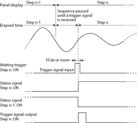
• Waiting trigger (TRIG.IN)
If set to “ON,” the sequence will be paused after the previous step is finished, and the PCR-LE Series will wait for a trigger. If a trigger signal (pulse width of at least 10 μs) is received through the SEQ TRIG IN terminal, the paused is released, and the step is executed.
While waiting for the trigger, the screen shows the next step number. The elapsed time remains at zero until the next step starts.
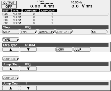
5: Jump function
Use this screen to set the step type, jump destination step, and number of times to jump.
|
Item |
Title |
Description |
|
|
TYPE |
NORM |
Step Type |
After this step is completed, the subsequent step will be executed. |
|
JUMP |
After this step is completed, the specified step will be executed. |
||
|
JUMP STEP |
Jump Step |
Sets the jump destination step (0 to 599) |
|
|
JUMP CNT |
Jump Count |
Sets the number of jump repetitions (1 to 99999; 99999 indicates unlimited repetitions) |
|
Jump function
The steps in a sequence are normally executed in order starting with the starting step. However, you can use the jump feature to skip over steps and repeat sets of steps by repeatedly executing jumps.
If the step execution time of the jump origin or jump destination step is less than 500 ms, the peaks of the output voltage waveform of the step that will be executed next may be clipped.
The PCR-LE Series automatically adjusts the power supply voltage (Vcc) of the linear amplifier. If you set the execution time of the jump origin step to a value less than 500 ms, the PCR-LE Series cannot perform this automatic adjustment. If the peaks of the output voltage waveform are clipped, set the execution time of the previous step to 500 ms or greater, or fix the internal Vcc.
• Example of not using the jump function
If you set TYPE to “NORM,” both JUMP and JUMP CNT will be disabled.
|
Step |
TYPE |
JUMP |
JUMP CNT |
|
1 to 8 |
NORM |
0 |
1 |

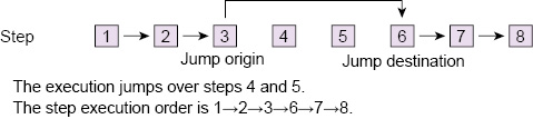
• Example of using the jump function (with no repetitions)
|
Step |
TYPE |
JUMP |
JUMP CNT |
|
1, 2, and 4 to 8 |
NORM |
0 |
1 |
|
3 |
JUMP |
6 |
1 |
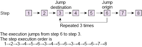
• Example of using the jump function (with repetitions)
|
Step |
TYPE |
JUMP |
JUMP CNT |
|
1 to 5, 7, and 8 |
NORM |
0 |
1 |
|
6 |
JUMP |
3 |
3 |
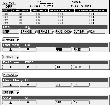
6: Starting phase angle, ending phase angle, sudden phase change, and output impedance
Use this screen to set the starting phase angle, ending phase angle, sudden phase change, and output impedance.
|
Item |
Title |
Description |
|
|
S.PHASE |
FREE |
Start Phase |
Does not set the starting phase angle |
|
FIXED |
Sets the starting phase angle (0 deg to 359 deg) |
||
|
E.PHASE |
FREE |
End Phase |
Does not set the ending phase angle |
|
FIXED |
Sets the ending phase angle (0 deg to 359 deg) |
||
|
PHAS. CHG*1 |
OFF |
Phase Change |
Does not set the sudden phase change |
|
ON |
Sets the sudden phase change |
||
|
OUT IMP. |
OFF |
Out Z |
Does not set the output impedance |
|
ON |
Sets the output impedance (output resistance as a percentage: 1 % to 100 %) |
||
*1. In the same step, do not turn on both the trigger wait setting (TRIG.IN) and the sudden phase change setting. If you do, the sequence cannot be executed.
- Memo -
Setup example for making sudden phase changes
Appendix A in the supplied CD-R operation manual contains sequence tutorials that explain sequence creation basics, phase angle settings, sudden phase changes, and multi-phase operation.
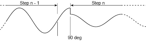
First, set the ending phase angle of the step immediately before the sudden phase change to 90 deg. If the sudden phase change is set to off, the sequence moves to the next step when the phase angle reaches 90 deg after the step time of the previous step elapses, as shown below.
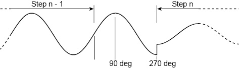
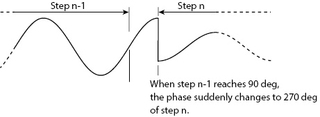
Lastly, set the sudden phase change to on. When the phase angle of the previous step reaches 90 deg, the sequence changes to the next step. The next step begins at 270 deg.
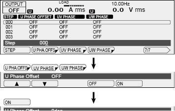
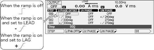
7 Setting the phase difference during single-phase, three-wire output and three-phase output (optional)
Display only when the 2P05-PCR-LE or 3P05-PCR-LE (optional) is in installed.
Set the phase difference from the U phase that is used when the PCR-LE Series switches to the next step.
Set this when only one or two phases are to change suddenly or when performing a phase sweep.
|
Item |
Title |
Description |
|||
|
U PHA.OFFS |
OFF |
U Phase Offset |
The U phase offset is not set. |
||
|
ON |
|
Sets the U phase offset (0 deg to 359 deg). |
|||
|
RAMP |
LEAD |
Sets the U phase change to leading. |
|||
|
LAG |
Sets the U phase change to lagging. |
||||
|
RAMP OFF |
Disables the ramped U phase change. |
||||
|
UV PHASE |
OFF |
UV Phase |
The phase difference between U and V is not set. There is no change from the previous step. |
||
|
ON |
|
Sets the phase difference between U and V (0 deg to 359 deg). |
|||
|
RAMP |
LEAD |
Sets the V phase change to leading. |
|||
|
LAG |
Sets the V phase change to lagging. |
||||
|
RAMP OFF |
Disables the ramped V phase change. |
||||
|
UW PHASE |
OFF |
UW Phase |
The phase difference between U and W is not set. There is no change from the previous step. |
||
|
ON |
|
Sets the phase difference between U and W (0 deg to 359 deg). |
|||
|
RAMP |
LEAD |
Sets the W phase change to leading. |
|||
|
LAG |
Sets the W phase change to lagging. |
||||
|
RAMP OFF |
Disables the ramped W phase change. |
||||
*1. Three-phase output (optional) only
U phase offset setting.
If you set the U phase offset, the U phase will be offset from the reference phase. As a result, the U-V/U-W phase difference settings will be offset from the actual phase difference.
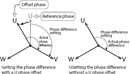
To avoid confusion, we recommend that you turn off the U phase offset when you use the phase sweep feature. For details, see “Phase setting for multi-phase output” in the sequence tutorial of the appendix.
Ramp setting
Phase ramp can be set to leading (LEAD) or lagging (LAG). This is effective for varying the line voltage.
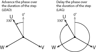
Set an absolute angle for the phase angle.
For details, see “Phase sweep” in the sequence tutorial of the appendix.
The items that you set here are shared between all steps.
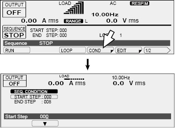
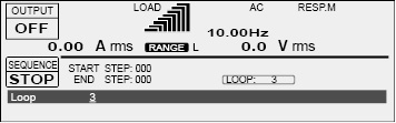
Setting the starting step number and the ending step number
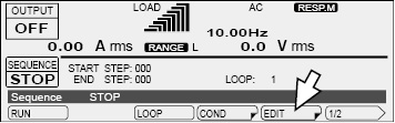
On the sequence screen, press COND (F4) to set the starting step number and the ending step number.
|
Item |
Title |
Description |
|
START STEP |
Start Step |
Sets the starting step number (0 to 599) |
|
END STEP |
End Step |
Sets the ending step number (0 to 599) |
Setting the number of repetitions
On the sequence screen, press LOOP (F3) to set the number of times that the sequence will be repeated.
|
Item |
Title |
Description |
|
LOOP |
Loop |
Sets the number of repetitions (1 to 99999; 99999 indicates unlimited repetitions) |
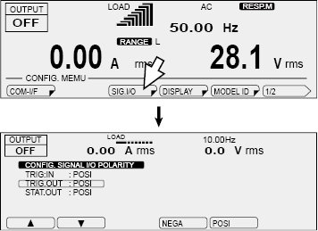
Setting the polarity of trigger and status output
Press CONFIG (SHIFT+OPR MODE) and then SIG.I/O (F3) to set the trigger input polarity, the trigger output polarity, and the status output polarity. The status signal polarity setting is shared with that of the power line abnormality simulation function.
|
Item |
Description |
|
|
TRIG.IN |
NEGA |
Sets the trigger input to falling edge |
|
POSI |
Sets the trigger input to rising edge |
|
|
TRIG.OUT |
NEGA |
Sets the trigger output to falling edge |
|
POSI |
Sets the trigger output to rising edge |
|
|
STAT.OUT |
NEGA |
Sets the status output to low level |
|
POSI |
Sets the status output to high level |
|
Executing, pausing, and stopping sequences
After you have finished setting the steps and the sequence conditions, you can execute the sequence.
On the sequence screen, press “RUN” (F1) to execute the sequence.
You cannot execute the sequence in the following situations.
• When the voltage range is set to the L range and there is a step whose voltage exceeds the output voltage setting range (Switch the range to the H range, or set the output voltage so that it is within the L range).
• When you have configured the PCR-LE Series so that it does not turn output off when the current limit is exceeded (DISABLE).
• When the regulation adjustment or soft sensing compensation function is in use.
• When the L range is selected and a step’s ACVolt or DCVolt setting is outside of the L range.
• When the voltage or frequency is set to a value outside the corresponding limits.
• If there is a step where the trigger wait setting (TRIG.IN) and the sudden phase change setting (PHAS.CHG) are both turned on.
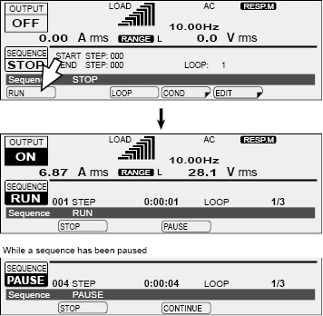
|
Item |
Title |
Description |
|
STOP |
Sequence |
Stops a sequence that is being executed |
|
PAUSE |
Pauses a sequence that is being executed |
|
|
CONTINUE |
Resumes a sequence that has been paused |
You can also resume the execution of a sequence that has been paused by applying a trigger signal to the SEQ TRIG IN terminal.
A sequence is complete when all steps are complete. The output state when the sequence is complete is the state specified in the last step.
If you want the output to turn off when the sequence is complete, you need to add a last step that turns the output off.
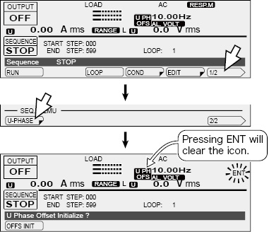
If the U phase is offset in the last step of the sequence (option), the offset (the U PH OFS icon) will remain even when the sequence is complete. Be sure to press 1/2 and then U PHASE on the sequence screen to clear the offset. The icon will disappear when you clear the offset.
![]() AC power supply PCR-LE series
AC power supply PCR-LE series
Advanced