AC power supply PCR-LE series
Advanced
In AC mode, you can simulate power supply line errors by stopping the PCR-LE Series output (to simulate power failures) and decreasing and increasing the voltage (to simulate voltage dips and pops).
Using Power Line Abnormality Simulations (Cont.)
Executing and stopping power line abnormality simulations
You can use this to test switching power supplies and other electronic devices.
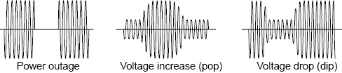
A sine wave is generated during the power line abnormality simulations. Even if you have set a special waveform, a sine wave will be generated as soon as you execute the power line abnormality simulation.
You can set these values while output is on or off.
|
Parameter |
Description |
|
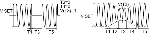
T1 |
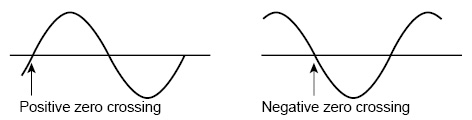
This is the voltage regulation start time or the voltage regulation start phase. This is the time or the phase from the waveform’s positive zero crossing (the point where the signal crosses the zero axis) to the point where voltage regulations - such as increases or decreases - start to occur. |
|
T2 |
This is slope time 1. For pops, this indicates how much time is required to raise the voltage to the pop voltage. For dips, this indicates how much time is required to lower the voltage to the dip voltage. |
|
T3 |
This is the voltage regulation time. For pops, this indicates the length of time that the voltage will be kept at the voltage that it has been raised to (the pop voltage). For dips, this indicates the length of time that the voltage will be kept at the voltage that it has been lowered to (the dip voltage). |
|
T4 |
This is slope time 2. For pops, this indicates how much time is required to lower the voltage from the pop voltage to the voltage that is in use during the period indicated by T5. For dips, this indicates how much time is required to raise the voltage from the dip voltage to the voltage that is in use during the period indicated by T5. |
|
T5 |
This is the return time or the number of return cycles. This indicates how long (either as a length of time or as a number of cycles of the present frequency) the voltage will be kept at the level that it returns to after a pop or dip is completed. |
|
T3VOLT |
This is regulated voltage. For pops, this is the voltage level that the voltage will be raised to (the pop voltage). For dips, this is the voltage level that the voltage will be lowered to (the dip voltage). |
|
LOOP |
This is the number of repetitions. This indicates the number of times that the sequence of steps defined by T1 to T5 will be repeated. |
- Memo -
Voltage regulation start polarity
You can set the zero crossing (the time at which the voltage becomes zero) that will be the reference for T1 to positive zero crossing or negative zero crossing by switching the voltage regulation start polarity (POL). You can use this function to change the phase by 180 °. The PCR-LE Series displays the output voltage (waveform) of L of the OUTPUT terminal block, with N as its reference.
|
1 |
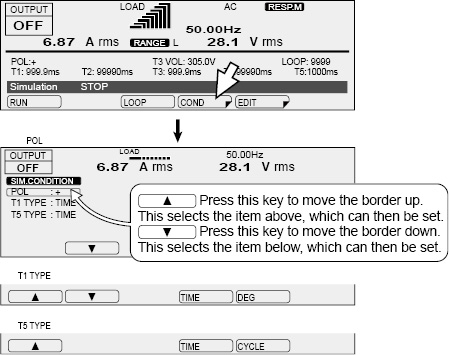
Set the steady-state voltage and frequency. |
|||||||||||||||||||||||||||
|
2 |
Press SIM and then COND (F4) to set the conditions. After you have finished configuring the settings, press ESC. A border is displayed around the item that you are setting. Press ▲ (to select the upper item) and ▼ (to select the lower item) to switch between items.
|
|||||||||||||||||||||||||||
|
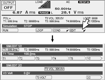
3 |
Press EDIT (F5) to set the parameters (T1 to T5 and T3 VOLT). After you have finished configuring the settings, press ESC.
*1. Depending on how T1 to T4 are set, this may lead or lag by one cycle. |
|||||||||||||||||||||||||||
|
4 |
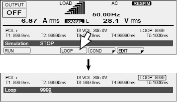
Select LOOP (F3) to set the number of repetitions.
|
|||||||||||||||||||||||||||
You cannot execute power line abnormality simulations in the following situations.
• In DC mode or AC+DC mode.
• When you have configured the PCR-LE Series so that it does not turn output off when the current limit is exceeded (DISABLE).
• When the regulation adjustment or soft sensing compensation function is in use.
• When the L range is selected and T3 VOLT is set to a value outside of its range.
• When T3 VOLT is set to a value outside the voltage limits.
|
1 |
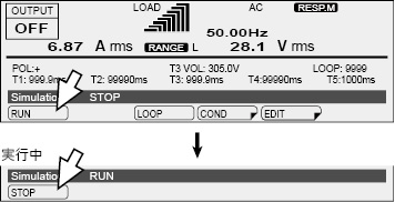
Press OUTPUT to turn output on. |
|
2 |
Press SIM and then RUN (F1) to execute a power line abnormality simulation. During execution, press STOP (F1) to stop the simulation.
|
Status signals are only generated during the periods defined by T2, T3, and T4 (period T3 when T2 and T4 both equal zero).
During single-phase, three-wire output or three-phase output (optional), status signals are output to the U-phase unit.
Signals are generated from the SEQ STAT OUT terminal (a BNC connector) on the rear panel of the PCR-LE Series. Use the configuration settings to set the signal polarity. “H” is approximately 5 V. “L” is approximately 0 V.
The BNC connector is isolated from the PCR-LE Series’ INPUT and OUTPUT terminal blocks. However, the common line of the TRIG and STAT signals is shared internally, so it is not isolated from the BNC connector. Also, the BNC connector is not isolated from the SLOT internal circuits. There is a slight time difference (approximately 100 ms) between the status signal output and changes to the actual output.
Status signals may be output when you change the settings of the various parameters.
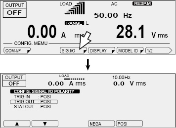
Press CONFIG (SHIFT+OPR MODE) and then SIG.I/O (F3) to set the status output polarity. The status signal polarity setting is shared with the sequence function.
|
Item |
Description |
|
|
STAT.OUT |
NEGA |
Sets the status output to low level |
|
POSI |
Sets the status output to high level |
|
![]() AC power supply PCR-LE series
AC power supply PCR-LE series
Advanced