AC power supply PCR-LE series
Basic
“What to do if the breaker trips
The PCR-LE Series has the following protection functions.
Input voltage drop protection
Overheat protection (OHP)
Overload protection
Internal semiconductor protection (OCP)
Output undervoltage protection (UVP)
Output overvoltage protection (OVP)
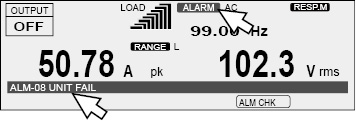
If a protection function is activated, an alarm sounds, “ALARM” is displayed on the screen, and the output is turned off.
During master-slave parallel operation(optional), if an alarm occurs on one unit, the entire system’s output will be turned off.
Press ALM CLR (SHIFT+CLR) to clear the alarm, and then fix the problem that caused the alarm.
If an alarm still occurs even after you have corrected all the causes of alarms, the PCR-LE Series may be malfunctioning. Stop using it immediately, and contact your Kikusui agent or distributor. Inform the individual that you contact of the alarm code that is displayed.
If the input voltage drops lower than the rating, the input voltage drop protection function is activated, and an alarm (AC INPUT LOW) is generated. Adjust the input voltage so that it is within the range in the specifications. If the input power supply wiring is long, use wires that have a large diameter to make the voltage drops smaller.
If the internal temperature rises to an abnormal level, the overheat protection is activated, and an alarm (ALM-02: OHP) is generated. Leave the PCR-LE Series on, and wait for approximately 10 minutes.
If the alarm has stopped occurring after 10 minutes, the PCR-LE Series may have been installed incorrectly, or the dust filter may be clogged.
If there are no problems with the installation or the dust filter, stop using the PCR-LE Series immediately, and contact your Kikusui agent or distributor to request repairs.
If the output current exceeds the rated current or the current limit, the overload protection is activated, and an alarm is generated (ALM-06: OVERLOAD).
During reverse power flow, the protection is activated at 30% of the rated current or the current limit, whichever is less.
You can set how the PCR-LE Series acts when the current limit is exceeded.
Output undervoltage protection (UVP) and output overvoltage protection (OVP)
UVP and OVP judgment varies depending on the voltage mode.
AC mode: Judgment is based on the rms voltage measurements.
DC mode: Judgment is based on the averaged voltage measurements.
AC+DC mode: Judgment is based on both the rms and averaged voltage measurements.
• Output undervoltage protection (UVP)
If the output voltage drops below the UVP setting and remains there for approximately 1 second, the output undervoltage protection will be activated. An alarm (ALM-07: UVP) will be generated.
• Output overvoltage protection (OVP)
If the output voltage exceeds the OVP setting and remains there for approximately 1 second, the output overvoltage protection will be activated. An alarm (ALM-00: OVP) will be generated.
• Setting UVP and OVP
In AC mode, specify an rms value. In DC mode, specify an average value.
In AC+DC mode, specify an rms value. To set an average value, change to DC mode, set the average value, and then return to AC+DC mode.
For single-phase three-wire output and three-phase output (optional), set the limits using phase voltages.
During single-phase three-wire output and three-phase output (optional), set the limits using phase voltages.
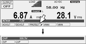
To set the OVP value, press V, PROTECT (F3), and then OVP (F1).
To set the UVP value, press V, PROTECT (F3), and then UVP (F2).
If PROTECT(F3) does not appear, hold down F6 until it appears.
|
Item |
Title |
Description |
|
OVP |
OVP |
Sets the OVP value (0.0 V to 474.1 V in AC mode and AC+DC mode, -474.1 V to 474.1 V in DC mode) |
|
UVP |
UVP |
Sets the UVP value (0.0 V to 474.1 V in AC mode and AC+DC mode, -474.1 V to 474.1 V in DC mode) |
Internal semiconductor protection (OCP)
This protection function protects the internal semiconductors of the PCR-LE Series. The internal semiconductor protection function will not be activated if you follow the PCR-LE Series usage guidelines outlined in the specifications. If a temporary overcurrent - such as an inrush current - occurs, the internal semiconductor protection function will be activated. If the internal semiconductor protection function remains activated for a set amount of time, an alarm (ALM-03: OCP) will be generated.
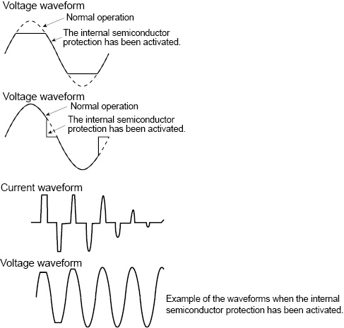
If the internal semiconductor protection function is activated, the output voltage waveform will be distorted.
In AC mode, you can set the time that elapses after the internal semiconductor protection function is activated before an alarm is generated. An alarm will only be generated if the internal semiconductor protection function circuit remains activated continually for the specified length of time. This is useful when you don’t want alarms to be generated due to short-term overloads such as those caused by inrush current.
In DC mode and AC+DC mode, an alarm is generated 1 second after the internal semiconductor protection is activated.
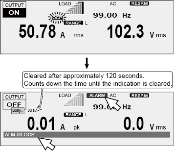
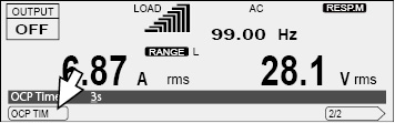
“OCP” is displayed when the internal semiconductor protection is activated.
After the alarm is generated, there is a period of approximately 120 seconds (the “Busy” state) during which the output cannot be turned on. The time until the “Busy” indication is cleared is displayed. The time until the “Busy” indication is cleared is displayed.
If the internal semiconductor protection is activated repeatedly, the PCR-LE Series may malfunction.
Setting the time that elapses before an alarm is generated
In AC mode, you can set the time that elapses after the internal semiconductor protection has been activated (the amount of time during which the internal semiconductor protection is continually activated) before an alarm is generated.
The amount time that elapses before an alarm is generated may increase depending on the overload state.
Even if an alarm is not generated, the output voltage waveform will be distorted because the internal semiconductor protection circuit has been activated.
Press I, 1/2 (F6), and then OCP TIM (F1) to set the time that elapses before an alarm is generated.
|
Item |
Title |
Description |
Valid mode |
|
OCPTIM |
OCPTIME |
Sets the time that elapses after the internal semiconductor protection function is activated before an alarm is generated (1 s to 3 s) |
AC |
Dealing with alarms
If an alarm has occurred, follow the remedies shown below, wait for at least 1 minute, and then resume the operation.
If you remove the problem that caused the internal semiconductor protection to be activated, the alarm will be cleared automatically. While the internal semiconductor protection is activated, pressing ALM CLR (SHIFT+CLR) will not clear the alarm.
• Linear load
If the current has exceeded the rated current, decrease the load.
If the power factor is low (the phase is lagging), use a phase-advancing capacitor or similar device to increase the power factor.
If the power factor is low (the phase is leading), connect a dummy resistance in parallel to the load to increase the power factor.
• Capacitor-input rectifier load
Decrease the peak current.
• Load that draw an inrush current
Decrease the inrush current.
Configure soft starts (the voltage rise time).
The PCR500LE and PCR1000LE do not have a breaker.
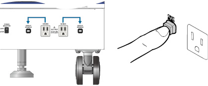
On the PCR2000LE, PCR3000LE, PCR4000LE, PCR6000LE, and PCR9000LE, if an output current of 10 A or greater flows from one of the outlets on the front panel, the breaker next to the outlet may trip, which will cut off the outlet’s output. If the breaker trips, the red button (the breaker button) will pop out.
The total output current that can be generated from the two outlets and the OUTPUT terminal block on the rear panel is the rated output current. If the rated value is exceeded, the overload protection function is activated.
For example, on the PCR4000LE, when the output voltage is 100 V (the 100 V range), the load power factor is 1, and the output frequency is 50 Hz, if an output current of 10 A is flowing from each outlet, the maximum output current that can be generated from the OUTPUT terminal block is (40 A - 10 A - 10 A =) 20 A.
|
1 |
Turn the POWER switch off. |
|
2 |
Press the breaker button in. |
|
3 |
Adjust the load so that the output current is less than or equal to 10 A. |
|
4 |
Turn the POWER switch on. |
![]() AC power supply PCR-LE series
AC power supply PCR-LE series
Basic