AC power supply PCR-LE series
Basic
“Voltage upper and lower limits
“Frequency upper and lower limits
“Current limit and peak current limits
Voltage upper and lower limits
Limits can be placed on the PCR-LE Series output setting. They prevent damage to the load caused by mistaken operations. You can set limits in advance according to the load conditions.
After you set the voltage limits, you will no longer be able to specify voltage values that are outside of the range that you have set. The only exception is 0 V. You can still use the numeric keypad to specify this value.
Set the limits so that the lower limit is less than or equal to the upper limit.
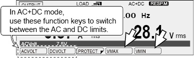
In AC+DC mode, there are AC limits and DC limits. Check the title in the entry area, and then set the value.
During single-phase, three-wire output and three-phase output (optional), set the limits using phase voltages.
To set the voltage upper limit, press V and then VMAX (F4).
To set the voltage lower limit, press V and then VMIN (F5).
|
Item |
Title |
Description |
Valid modes |
|
VMAX |
ACVoltMax AC PhaseVoltMax*1 |
Sets the AC voltage upper limit (0.0 V to 305.0 V) |
AC and AC+DC |
|
DCVoltMax DC PhaseVoltMax*1 |
Sets the DC voltage upper limit (-431.0 V to 431.0 V) |
DC and AC+DC |
|
|
VMIN |
ACVoltMin AC PhaseVoltMin*1 |
Sets the AC voltage lower limit (0.0 V to 305.0 V) |
AC and AC+DC |
|
DCVoltMin DC PhaseVoltMin*1 |
Sets the DC voltage lower limit (-431.0 V to 431.0 V) |
DC and AC+DC |
*1. The display during single-phase, three-wire output and three-phase output (optional)
Frequency upper and lower limits
Limits can be placed on the PCR-LE Series output setting. They prevent damage to the load caused by mistaken operations. You can set limits in advance according to the load conditions.
After you set the frequency limits, you will no longer be able to specify frequency values that are outside of the range that you have set.
You cannot set these values in DC mode.
Set the limits so that the lower limit is less than or equal to the upper limit.
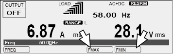
Press F and then FMAX (F4) to set the frequency upper limit.
Press F and then FMIN (F5) to set the frequency lower limit.
|
Item |
Title |
Description |
Valid modes |
|
FMAX |
FreqMax |
Sets the frequency upper limit (1.00 Hz to 999.9 Hz) |
AC and AC+DC |
|
FMIN |
FreqMin |
Sets the frequency lower limit (1.00 Hz to 999.9 Hz) |
Limits can be placed on the current that flows through the load. There is a current limit, a positive peak current limit, and a negative peak current limit. You can set limits according to the load conditions.
You can set the output current’s upper limit. You cannot set the lower limit.
The limit operates on the rms value of the output current.
You can set how the PCR-LE Series acts (turn the output off/ do not turn the output off) when the current limit is exceeded.
The actual current limit is activated at 1.1 times the rated current or the current limit, whichever is less. The rated current is automatically derated (reduced) depending on the output conditions (output voltage, frequency, and load power factor).For details of rated output current, see ”About the output and the load”.
• Positive peak current limit and negative peak current limit
You can set positive and negative peak current limits.
These instantly limit the peak output current.
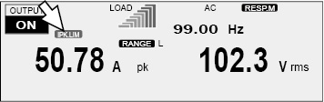
If the peak current approaches the peak current limit (approximately 94 % of the peak current limit), “IPK.LIM” is displayed.
Setting the peak current limits does not change the load level meter’s full scale.
|
Item |
Title |
Description |
|
|
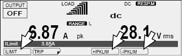
ILIMIT |
|
ILimit |
Sets the current limit (the rated current × 0.1 to the rated current × 1.1) |
|
U*1 |
U ILimit |
Sets the current limit of U phase (the rated current × 0.1 to the rated current × 1.1) |
|
|
V*1 |
V ILimit |
Sets the current limit of V phase (the rated current × 0.1 to the rated current × 1.1) |
|
|
W*2 |
W ILimit |
Sets the current limit of W phase (the rated current × 0.1 to the rated current × 1.1) |
|
|
+IPKMAX |
|
+IPKLimit |
Sets the positive peak current limit (the rated current × 0.1 to the rated current × 4.4) |
|
U*1 |
U +IPKLimit |
Sets the positive peak current limit of U phase (the rated current × 0.1 to the rated current × 4.4) |
|
|
V*1 |
V +IPKLimit |
Sets the positive peak current limit of V phase (the rated current × 0.1 to the rated current × 4.4) |
|
|
W*2 |
W +IPKLimit |
Sets the positive peak current limit of W phase (the rated current × 0.1 to the rated current × 4.4) |
|
|
-IPKMAX |
|
-IPKLimit |
Sets the negative peak current limit (the rated current × 0.1 to the rated current × 4.4) |
|
U*1 |
U -IPKLimit |
Sets the negative peak current limit of U phase (the rated current × 0.1 to the rated current × 4.4) |
|
|
V*1 |
V -IPKLimit |
Sets the negative peak current limit of V phase (the rated current × 0.1 to the rated current × 4.4) |
|
|
W*2 |
W -IPKLimit |
Sets the negative peak current limit of W phase (the rated current × 0.1 to the rated current × 4.4) |
|
*1. Single-phase three-wire output or three-phase output (optional) only
*2. Three-phase output (optional) only
|
|
Setting |
|
|
|
|
|||
|
Output mode |
PCR500LE |
PCR1000LE |
PCR2000LE |
PCR3000LE |
PCR4000LE |
PCR6000LE |
PCR9000LE |
|
|
Current limit*1 |
AC |
0.50 A to 5.50 A |
1.00 A to 11.00 A |
2.00 A to 22.00 A |
3.00 A to 33.00 A |
4.00 A to 44.00 A |
6.00 A to 66.00 A |
9.00 A to 99.00 A |
|
DC and AC+DC |
0.35 A to 3.85 A |
0.70 A to 7.70 A |
1.40 A to 15.40 A |
2.10 A to 23.10 A |
2.80 A to 30.80 A |
4.20 A to 46.20 A |
6.30 A to 69.30 A |
|
|
Positive peak current limit*2 |
All |
0.50 A to 22.00 A |
1.00 A to 44.00 A |
2.00 A to 88.00 A |
3.00 A to 132.0 A |
4.00 A to 176.0 A |
6.00 A to 264.0 A |
9.00 A to 396.0 A |
|
Negative peak current limit*2 |
-0.50 A to -22.00 A |
-1.00 A to -44.00 A |
-2.00 A to -88.00 A |
-3.00 A to -132.0 A |
-4.00 A to -176.0 A |
-6.00 A to -264.0 A |
-9.00 A to -396.0 A |
|
*1. The current that can actually be supplied is 1.1 times the rated current or the current limit, whichever is less. See ”Rated output current characteristics (Derating)”.
*2. The current that can actually be supplied is the maximum peak current or the current limit, whichever is less. For details of maximum peak current, see “AC mode output (AC rms)”.
Action to perform when the current limit is exceeded
You can set the action to perform (whether the output is turned off) when the current exceeds the current limit. In AC mode, you can set the time that elapses before the output is turned off when the current limit is exceeded.
The current limit function operates on the rms value of the current.
Action: Turn the output off (ENABLE)
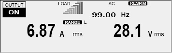
• The limit has not been exceeded
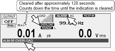
• The limit has been exceeded
In AC mode, the output is turned off after the specified trip time has elapsed.
In DC mode and AC+DC mode, the output is turned off 1 second after the limit has been exceeded.
There is a delay in the response depending on the aperture time setting. After the output is turned off, there is a period of approximately 120 seconds (the “Busy” state) during which the output cannot be turned on.
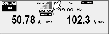
Action: Do not turn the output off (DISABLE)
• The limit has not been exceeded
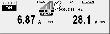
• The limit has been exceeded
The output voltage is controlled so that the current limit is not exceeded.
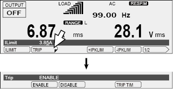
Press I and then TRIP (F2) to select the action to perform when the limit is exceeded.
|
Item |
Title |
Description |
|
ENABLE |
Trip |
If the current exceeds the current limit for more than a set amount of time, “OVERLOAD” lights, the output is turned off, and an alarm (ALM-06: OVERLOAD) is generated. |
|
DISABLE |
If the current is less than the current limit, “TRIP DIS.” lights. If a current that is greater than the current limit flows, “OVERLOAD” lights, and the output voltage is controlled so that the current does not exceed the current limit.*1
|
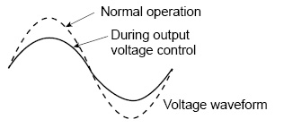
*1. This is calculated as an rms value. The current limit may be exceeded for a few seconds because of the relationship between the measurement processing time and the voltage resolution. The current may oscillate (increase and decrease) while it is being controlled.
If you have selected ENABLE (to turn the output off)
To clear the alarm, press ALM CLR (SHIFT+CLR).
 CAUTION
Risk of product malfunction. If an overload occurs, be sure to remove the cause of the problem, and then press OUTPUT.
If you have selected DISABLE (to not turn the output off)
If you have selected to not turn the output off (DISABLE), you will not be able to:
Turn soft start on (set the rise time).
Execute power line abnormality simulations.
Execute sequences.
Use the compensation function’s software sensing and regulation adjustment.
- Note -
If the load short-circuits, if an extreme overload occurs, or if the difference between the output voltage and the output voltage setting during output voltage control is large (the output voltage setting is high), (1) the internal semiconductor protection (OCP) may be activated and the output voltage waveform may be distorted or (2) an alarm (ALM-03: OCP) may occur.
Setting the time (Trip time) that elapses before the output is turned off when the current limit is exceeded
In AC mode, you can set the amount of time that elapses after the current limit is exceeded (the amount of time during which the current limit is continuously exceeded) before the output is turned off. This is useful when you don’t want the output to be turned off due to issues such as inrush current causing short-term overloads.
If the voltage setting is at or lower than 10 V (L range) or 20 V (H range), the output will turn off after 3 s even if you set the trip time to 4 s or longer.
The amount time until the output is turned off may become large due to the state of the load or the timing of the PCR-LE Series internal current measurement. There is a delay in the response depending on the aperture time setting.
If the full scale bar of the load level meter continues to be lit, the temperature inside the PCR-LE is high. If an overload occurs repeatedly, the time until the output is turned off may be shortened.
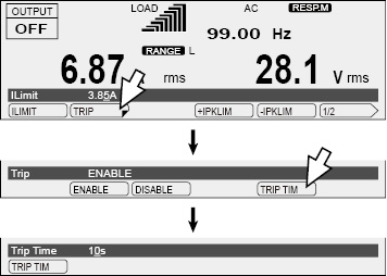
Press I, TRIP (F2), and then TRIP TIM (F5) to set the time that elapses before the output is turned off.
|
Item |
Title |
Description |
Valid mode |
|
TRIP TIM |
Trip Time |
Sets the time that elapses (0 s to 10 s) before the output is turned off when the current limit is exceeded |
AC |
![]() AC power supply PCR-LE series
AC power supply PCR-LE series
Basic