AC power supply PCR-LE2 series
Specifications
Unless specified otherwise, the specifications are for the following settings and conditions.
The warm-up time is 30 minutes (with current flowing).
TYP: These are typical values that are representative of situations where the PCR-LE2 Series operates in an environment with an ambient temperature of 23 °C (73.4 °F). These values do not guarantee the performance of the PCR-LE2 Series.
set: Indicates a setting.
reading: Indicates the readout value.
|
|
PCR6000LE2 |
PCR9000LE2 |
PCR12000LE2 |
PCR18000LE2 |
PCR27000LE2 |
|
|
Nominal input voltage |
Single-phase two-wire input |
200 Vac to 240 Vac |
--- |
--- |
--- |
--- |
|
Three-phase three-wire input |
200 Vac to 240 Vac |
|||||
|
Three-phase Four-wire input |
220 Vac to 240 Vac (Phase voltage) |
|||||
|
Input voltage range |
Single-phase two-wire input |
170 Vac to 250 Vac |
--- |
--- |
--- |
--- |
|
Three-phase three-wire input |
170 Vac to 250 Vac |
|||||
|
Three-phase four-wire input |
187 Vac to 254 Vac (Phase voltage) |
|||||
|
Nominal input Frequency |
50 Hz to 60 Hz |
|
||||
|
Input frequency range |
47 Hz to 63 Hz |
|
||||
|
Apparent power*1 |
Approx. 10.6 kVA |
Approx. 15.7 kVA |
Approx. 23 kVA |
Approx. 33 kVA |
Approx. 48 kVA |
|
|
Power factor *1 |
0.97 (TYP) |
|
||||
|
Maximum current*2 |
Single-phase two-wire input |
64 A |
--- |
--- |
--- |
--- |
|
Three-phase three-wire input |
38 A |
55.0 A |
75 A |
111 A |
165 A |
|
|
Three-phase four-wire input |
21 A |
30 A |
39 A |
59 A |
91 A |
|
*1. When the output phase voltage is 100 V or 200 V, the output current is the rated value, the load power factor is 1, and the output frequency is between 40 Hz and 999.9 Hz.
*2. When the input voltage is 170 V (Single phase two-wire input and Three-phase-three-wire input), 187 V (Three-phase Four-wire input).
|
|
PCR6000LE2 |
PCR9000LE2 |
PCR12000LE2 |
PCR18000LE2 |
PCR27000LE2 |
|
|
Phase voltage (output L range, output H range) |
Rating |
1 V to 150 V, 2 V to 300 V |
||||
|
Setting range |
0 V to 152.5 V, 0 V to 305.0 V |
|||||
|
Resolution |
0.1 V |
|||||
|
Accuracy*1 |
±(0.3 % of set + 0.6 V) |
|||||
|
Maximum current (output L range, output H range)*2 |
Single-phase output |
60 A, 30 A |
90 A, 45 A |
120 A, 60 A |
180 A, 90 A |
270 A, 135 A |
|
Single-phase three-wire output, Three-phase output |
20 A, 10 A |
30 A, 15 A |
40 A, 20 A |
60 A, 30 A |
90 A, 45 A |
|
|
Phase |
Single-phase Two-wire, Single-phase Three-wire, and Three-phase Four-wire |
|||||
|
Power capacity |
Single-phase output, Three-phase output |
6 kVA |
9 kVA |
12 kVA |
18 kVA |
27 kVA |
|
Single-phase three-wire output |
4 kVA |
6 kVA |
8 kVA |
12 kVA |
18 kVA |
|
|
Maximum peak current |
Maximum current (rms) x 4 (TYP) *3 |
|||||
|
Maximum reverse current *4 |
30 % of the maximum current (rms) |
|||||
|
Load power factor |
0 to 1 (leading or lagging) *2 |
|||||
|
Frequency *2 |
Setting range |
1 Hz to 999.9 Hz*5 |
||||
|
Resolution |
0.01 Hz (1.00 Hz to 100.0 Hz), 0.1 Hz (100.0 Hz to 999.9 Hz) |
|||||
|
Accuracy |
±1×10⁻⁴ |
|||||
*1. When the output frequency is between 45 Hz and 65 Hz, with no load, and at 23°C±5°C.
*2. When the output phase voltage is between 1 V and 100 V (L range) or 2 V and 200 V (H range) and the load power factor is between 0.8 and 1.
When the output phase voltage is between 100 V and 150 V (L range) or 200 V and 300 V (H range), the output current is reduced by the output phase voltage.
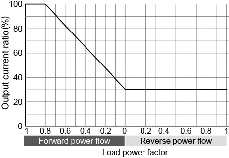
When the load power factor is between 0 and 0.8, the output current is reduced by the load power factor.
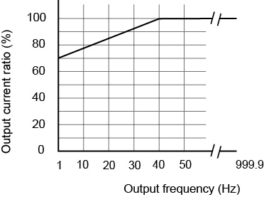
When the output frequency is between 1 Hz and 40 Hz, the output current is reduced by the output frequency.
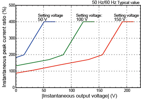
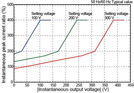
*3. For capacitor-input rectifier loads, (at near the peak of the voltage waveform, excluding three-phase three-wire output).
The peak current that can be output decreases in accordance with the reduction in the absolute value of the instantaneous output voltage.
“Instantaneous output voltage versus instantaneous peak current ratio” (figs 5 and 6) for the representative voltage settings of each range is indicated in “Rated output current characteristics (Derating)”.
*4. When the output phase voltage is 100 V or 200 V and the output frequency is between 40 Hz and 999.9 Hz (current is -90 deg to -180 deg/ 90 deg to 180 deg out of phase with the output voltage).
*5. The frequency is limited to the range from 1 Hz to 500.0 Hz while three-phase output in the PCR-LE 500Hz LMT models.
|
|
PCR6000LE2 |
PCR9000LE2 |
PCR12000LE2 |
PCR18000LE2 |
PCR27000LE2 |
|
|
Phase voltage (output L range, output H range) |
Rating |
-1.4 V to -212 V and +1.4 V to +212 V, -2.8 V to -424 V and +2.8 V to +424 V |
||||
|
Setting range |
-215.5 V to +215.5 V, -431.0 V to +431.0 V |
|||||
|
Resolution |
0.1 V |
|||||
|
Setting accuracy |
±(0.05 % of set + 0.05 V / 0.1 V) |
|||||
|
Maximum current (output L range, output H range) *2 |
Single-phase output |
42 A, 21 A |
63 A, 31.5 A |
84 A, 42 A |
126 A, 63 A |
189 A, 94.5 A |
|
Single-phase three-wire output Three-phase output |
14 A, 7 A |
21 A, 10.5 A |
28 A, 14 A |
42 A, 21 A |
63 A, 31.5 A |
|
|
Maximum instantaneous current*3 |
Maximum current (rms) × 3.6 |
|||||
|
Power capacity |
Single-phase output |
4.2 kW |
6.3 kW |
8.4 kW |
12.6 kW |
18.9 kW |
|
Single-phase three-wire output Three-phase output |
2.8 kW |
4.2 kW |
5.6 kW |
8.4 kW |
12.6 kW |
|
*1. With no load at 23°C±5°C.
*2. When the output phase voltage is between 100 V and 212 V (L range) or 200 V and 424 V (H range), the output current is reduced by the output phase voltage.
*3. Limited by the rated output current's rms value.
|
|
Setting range |
Resolution |
Setting accuracy |
|
Voltage setting |
The AC voltage setting range is the same as the range in AC mode. The DC voltage setting range is the same as the range in DC mode. However, the peak AC+DC voltage must be within the DC voltage setting range. |
AC voltage setting + DC voltage setting |
|
|
Maximum current |
The same as the setting in DC mode |
||
|
Maximum instantaneous current |
|||
|
Power capacity |
The same as the setting in DC mode |
||
|
Frequency |
The same as the setting in AC mode |
||
|
|
PCR6000LE2 |
PCR9000LE2 |
PCR12000LE2 |
PCR18000LE2 |
PCR27000LE2 |
|
Line regulation*1 |
Within ±0.1 % |
||||
|
Load regulation*2 |
Within ±0.3 V |
Within ±0.5 V |
|||
|
Output frequency variation*3 |
Within ±0.5 % |
Within ±1 % |
|||
|
Ripple noise in DC mode (5 Hz to 1 MHz components) |
0.25 Vrms or less |
0.5 Vrms or less |
|||
|
Ambient temperature variation *4 |
±100 ppm/ °C (TYP) |
||||
*1. With respect to changes in the rated range of input voltage
*2. With respect to 0 % to 100 % changes in the rating of output current
When the output phase voltage is between 80 V and 150 V (L range) or 160 V and 300 V (H range) and the load power factor is 1. At the output terminal block. When the response mode is set to MEDIUM.
*3. Between 40 Hz and 999.9 Hz.
When the output phase voltage is between 80 V and 150 V (L range) or 160 V and 300 V (H range) and the load power factor is 1. This is the output line regulation with 200 Hz as the reference. When the response mode is set to MEDIUM.
*4. With respect to changes in the operating temperature range.
When the output phase voltage is 100 V or 200 V and the output current is 0 A.
Output frequency stability, output voltage waveform distortion ratio, output voltage response speed, efficiency, Phase difference of the output phase voltage
|
|
PCR6000LE2 |
PCR9000LE2 |
PCR12000LE2 |
PCR18000LE2 |
PCR27000LE2 |
|
|
Output frequency stability*1 |
Within ±5×10⁻⁵ |
|||||
|
Output voltage waveform distortion ratio *2 |
0.3 % or less |
0.5 % or less |
||||
|
Output voltage response speed *3 |
30 µs (TYP) |
50 µs (TYP) |
||||
|
Efficiency *4 |
58 % or more |
|||||
|
Phase difference of the output phase voltage *5 |
Resolution |
1° |
||||
|
Accuracy |
Within ±(0.4°+5 µs) Within ±(0.4°+fo×1.8×10⁻³°), where the output frequency is fo.*6 |
|||||
|
Range |
0° to 359° |
|||||
*1. For changes within the rated ranges of all specifications
*2. When the output phase voltage is between 80 V and 150 V (L range) or 160 V and 300 V (H range) and the load power factor is 1. When the response mode is set to MEDIUM.
*3. When the output phase voltage is 100 V or 200 V, the load power factor is 1, and the output current changes from 0 A to the rated value and from the rated value to 0 A. When the response mode is set to MEDIUM.
*4. When the output phase voltage is 100 V or 200 V, the output current is the rated value, the load power factor is 1, and the output frequency is between 40 Hz and 999.9 Hz.
*5. Phase difference between output voltages (phase voltages) when each phase is considered along with the neutral point.
*6. The following show the angles obtained by calculating the expression with the specified frequency.
Within ±0.5° (when generating 60 Hz output)
Within ±1.2° (when generating 400 Hz output)
|
|
PCR6000LE2 |
PCR9000LE2 |
PCR12000LE2 |
PCR18000LE2 |
PCR27000LE2 |
||
|
Voltmeter *1 |
Resolution |
0.1 V |
|||||
|
Accuracy *2 |
±(1 % of reading +2 digits) |
||||||
|
Ammeter *1 |
Resolution |
Single-phase output |
0.1 A |
0.1 A, 1 A |
|||
|
Single-phase three-wire output Three-phase output |
0.01 A |
0.1 A |
|||||
|
Accuracy *3 |
±(1 % of reading +2 digits) |
||||||
|
Wattmeter *4 |
Resolution |
Single-phase output |
1 W |
1 W, 0.01 kW |
|||
|
Single-phase three-wire output Three-phase output |
0.1 W , 1 W |
1 W |
1 W, 0.01 kW |
||||
|
Accuracy *5 |
±(1 % of reading +3 digits) |
||||||
|
Frequency meter *6 |
Resolution |
0.01 Hz (1.00 Hz to 99.99 Hz) , 0.1 Hz (100.0 Hz to 999.9 Hz) |
|||||
*1. With the true rms display, a waveform with a crest factor of 3 or less, DC, output frequency between 45 Hz and 65 Hz, RMS, and AVE.
*2. 10 V to 848 V, and at 23°C±5°C.
*3. 5 % of the maximum rated current to maximum rated current, and at 23°C±5°C.
*4. When the output frequency is between 45 Hz and 65 Hz.
*5. 10 % to 100 % of the rated output capacity, when the load power factor is 1, and at room temperature.
*6. Displays the output frequency setting (frequency of the internal reference voltage)
Limit Values and Protection Functions
|
|
PCR6000LE2 |
PCR9000LE2 |
PCR12000LE2 |
PCR18000LE2 |
PCR27000LE2 |
||
|
Voltage |
AC voltage upper limit AC voltage lower limit |
0.0 V to 305.0 V |
|||||
|
DC voltage upper limit DC voltage lower limit |
-431.0 V to 431.0 V |
||||||
|
Output overvoltage protection AC/AC+DC mode |
0.0 V to 474.1 V |
||||||
|
utput overvoltage protection DC mode |
-474.1 V to 474.1 V |
||||||
|
Output undervoltage protection AC/AC+DC mode |
0.0 V to 474.1 V |
||||||
|
Output undervoltage protection DC mode |
-474.1 V to 474.1 V |
||||||
|
Resolution |
0.1 V |
||||||
|
Frequency |
Upper limit Lower limit |
1 Hz to 999.9 Hz, 500Hz LMT model: 1 Hz to 500 Hz (Three-phase output) |
|||||
|
Resolution |
0.01 Hz (1.00 Hz to 100.0 Hz), 0.1 Hz (100.0 Hz to 999.9 Hz) |
||||||
|
Current |
Current limit*1 AC mode |
Single-phase output |
6.00 A to |
9.00 A to |
12.00 A to |
18.00 A to |
27.00 A to |
|
Single-phase three-wire output Three-phase output |
2.00 A to |
3.00 A to |
4.00 A to |
6.00 A to |
9.00 A to |
||
|
Current limit*1 DC/AC+DC mode |
Single-phase output |
4.20 A to |
6.30 A to |
8.40 A to |
12.60 A to |
18.90 A to |
|
|
Single-phase three-wire output Three-phase output |
1.40 A to |
2.10 A to |
2.80 A to |
4.20 A to |
6.30 A to |
||
|
Positive peak current limit*2 |
Single-phase output |
6.00 A to |
9.00 A to |
12.00 A to |
18.00 A to |
27.00 A to |
|
|
Single-phase three-wire output Three-phase output |
2.00 A to |
3.00 A to |
4.00 A to |
6.00 A to |
9.00 A to |
||
|
Negative peak current limit*2 |
Single-phase output |
-6.00 A to |
-9.00 A to |
-12.00 A to -528.0 A |
-18.00 A to -792.0 A |
-27.00 A to -1188 A |
|
|
Single-phase three-wire output Three-phase output |
-2.00 A to |
-3.00 A to |
-4.00 A to |
-6.00 A to |
-9.00 A to |
||
|
Resolution*3 |
0.01 A (0.35 A to 100.0 A), 0.1 A (100.0 A to 1000 A), 1 A (1000 A to 1188 A) |
||||||
*1. The current that can actually be supplied is 1.1 times the rated current or the current limit, whichever is less.
*2. The current that can actually be supplied is the maximum peak current or the current limit, whichever is less.
*3. You can set the current in 0.01 A/ 0.1 A/ 1 A steps, but it may not change at this resolution depending on the relationship with the internal D/A resolution.
Power line abnormality simulations
|
|
Setting range |
Resolution |
Setting accuracy |
|
|
T1 |
DEG |
0 deg to 359 deg |
1 deg |
±1 deg |
|
TIME |
0.0 ms to 999.9 ms |
0.1 ms |
±(1×10⁻³+0.1 ms) |
|
|
T2 |
0.0 ms to 99990 ms |
0.1 ms |
±(1×10⁻³+0.1 ms) |
|
|
T3 |
0.1 ms to 9999.0 ms |
0.1 ms |
±(1×10⁻³+0.1 ms) |
|
|
T4 |
0.0 ms to 99990 ms |
0.1 ms |
±(1×10⁻³+0.1 ms) |
|
|
T5 |
0.0 ms to 99990 ms |
0.1 ms |
±(1×10⁻³+0.1 ms) |
|
|
N |
0 cycles to 999900 cycles |
1 cycle |
±1 cycle |
|
|
T3 VOLT |
The same as the output voltage setting range |
|||
|
LOOP |
0 to 9998 repetitions or infinite repetitions |
1 repetition |
±1 repetition |
|
|
|
Setting range |
Resolution |
Setting accuracy |
|
STEP |
0 to 599 |
1 |
--- |
|
FREQ |
The same as the output frequency setting range |
||
|
ACV |
The same as the output voltage setting range |
||
|
TIME |
0.1 ms to 1000 hour |
0.1 ms |
±(1×10⁻³+0.1 ms) |
|
W.B. No. |
The same as the special waveform output setting range |
||
|
IMPEDANCE |
The same as the output impedance setting range |
||
|
DCV |
The same as the output voltage setting range |
||
|
S.PHASE |
0 deg to 359 deg |
1 deg |
±1 deg |
|
E.PHASE |
0 deg to 359 deg |
1 deg |
±1 deg |
|
|
Setting range |
Resolution |
Setting accuracy |
|
Waveform bank |
0 to 63 (the waveform bank in 0 is read-only) |
1 |
--- |
|
Crest factor |
1.10 to 1.40 |
0.01 |
±0.01 |
|
|
Setting range |
Resolution |
Setting accuracy |
||||
|
Single-phase output |
Single-phase three-wire output, Three-phase output |
Single-phase output |
Single-phase three-wire output, Three-phase output |
Single-phase output |
Single-phase three-wire output, Three-phase output |
||
|
PCR6000LE2 |
L range |
0 Ω to 0.333 Ω |
0 Ω to 1.0 Ω |
3.33 mΩ |
10 mΩ |
±(10 % of set+6.67 mΩ) |
±(10 % of set+20 mΩ) |
|
H range |
0 Ω to 1.333 Ω |
0 Ω to 4.0 Ω |
13.33 mΩ |
40 mΩ |
±(10 % of set+26.67 mΩ) |
±(10 % of set+80 mΩ) |
|
|
PCR9000LE2 |
L range |
0 Ω to 0.222 Ω |
0 Ω to 0.667 Ω |
2.22 mΩ |
6.67 mΩ |
±(10 % of set+4.44 mΩ) |
±(10 % of set+13.33 mΩ) |
|
H range |
0 Ω to 0.889 Ω |
0 Ω to 2.667 Ω |
8.89 mΩ |
26.67 mΩ |
±(10 % of set+17.78 mΩ) |
±(10 % of set+53.32 mΩ) |
|
|
PCR12000LE2 |
L range |
0 Ω to 0.167 Ω |
0 Ω to 0.5 Ω |
1.67 mΩ |
5 mΩ |
±(10 % of set+3.33 mΩ) |
±(10 % of set+10 mΩ) |
|
H range |
0 Ω to 0.667 Ω |
0 Ω to 2.0 Ω |
6.67 mΩ |
20 mΩ |
±(10 % of set+13.33 mΩ) |
±(10 % of set+40 mΩ) |
|
|
PCR18000LE2 |
L range |
0 Ω to 0.111 Ω |
0 Ω to 0.333 Ω |
1.11 mΩ |
3.33 mΩ |
±(10 % of set+2.22 mΩ) |
±(10 % of set+6.67 mΩ) |
|
H range |
0 Ω to 0.444 Ω |
0 Ω to 1.333 Ω |
4.44 mΩ |
13.32 mΩ |
±(10 % of set+8..89 mΩ) |
±(10 % of set+26.67 mΩ) |
|
|
PCR27000LE2 |
L range |
0 Ω to 0.0741 Ω |
0 Ω to 0.222 Ω |
0.741 mΩ |
2.22 mΩ |
±(10 % of set+1.48 mΩ) |
±(10 % of set+4.44 mΩ) |
|
H range |
0 Ω to 0.296 Ω |
0 Ω to 0.889 Ω |
2.96 mΩ |
8.89 mΩ |
±(10 % of set+5.93 mΩ) |
±(10 % of set+17.78 mΩ) |
|
|
|
Setting range |
Resolution |
Setting accuracy |
|
Phase setting |
0 deg to 359 deg |
1 deg |
±1 deg |
Communication interface (RS232C)
|
Software protocol |
IEEE Std 488.2-1992 |
|
|
Command language |
Complies with SCPI Specification 1999.0 |
|
|
RS232C |
Complies with the EIA232D specifications D-SUB 9-pin connector (male, Use a cross cable (null modem cable)), |
|
|
|
Baud rate |
9600 bps/ 19200 bps/ 38400 bps |
|
Data length |
8 bit / 7 bit |
|
|
Stop bit |
1 bit / 2 bit |
|
|
Parity bit |
Fixed to none |
|
|
Flow control |
OFF/ RTS・CTS |
|
|
Message terminator |
LF |
|
|
Trigger input |
Pulse input for resuming the sequence function, BNC connector Photocoupler input, drive voltage: 5 V, DC resistance: approx. 470 Ω, active with 7 mA source, pulse width: 10 µs |
|
Trigger output |
Pulse output at the start of sequence step execution, BNC connector Open collector output, pulled up to +5 V with approx. 10 kΩ, DC resistance: 220 Ω, maximum sink current: 10 mA, pulse width: 10 µs |
|
Status output |
Output during periods T2, T3, and T4 in power line abnormality simulations and during a step output of the sequence function, BNC connector Open collector output, pulled up to +5 V with approx. 10 kΩ, DC resistance: 220 Ω, maximum sink current: 10 mA |
|
|
PCR6000LE2 |
PCR9000LE2 |
PCR12000LE2 |
PCR18000LE2 |
PCR27000LE2 |
|
|
Insulation resistance |
Between input and chassis, output and chassis, input and output |
500 Vdc, 10 MΩ or more |
||||
|
Withstand voltage |
Between input and chassis, output and chassis, input and output |
1.5 kVac for 1 minute |
||||
|
Circuit method |
Linear amplifier system |
|||||
|
Environmental conditions |
Operating environment |
Indoor use, overvoltage category II |
||||
|
Operating temperature range |
0 °C to +50 °C (32 °F to +122 °F) |
|||||
|
Storage temperature range |
-10 °C to +60 °C (14 °F to 140 °F) |
|||||
|
Operating humidity range |
20 %rh to 80 %rh (no condensation) |
|||||
|
Storage humidity range |
90 %rh or less (no condensation) |
|||||
|
Altitude |
Up to 2000 m |
|||||
|
Dimensions (chassis) |
See the outline drawing. |
|||||
|
Weight |
Approx. 140 kg (308.65 lb) |
Approx. 190 kg (418.88 lb) |
Approx. 350 kg (771.62 lb) |
Approx. 480 kg (1058.22 lb) |
Approx. 630 kg (1388.91 lb) |
|
|
Input terminal |
Single-phase two-wire input |
M8 |
--- |
--- |
--- |
--- |
|
Three-phase three/four-wire input |
M5 |
M8 |
||||
|
Output terminal |
Single-phase output |
M8 |
||||
|
Single-phase three-wire output, Three-phase output |
M5 |
M8 |
||||
|
Accessories |
Setup Guide |
1 copy |
||||
|
Quick Reference |
English: 1 copy, Japanese: 1 copy |
|||||
|
Safety information |
1 copy |
|||||
|
CD-ROM |
1 disc |
|||||
|
Electromagnetic compatibility (EMC)*1, *2 |
Complies with the requirements of the following directive and standards. EMC Directive 2014/30/EU EN 61326-1 (Class A*3 ) EN 55011 (Class A*3, Group 1*4 ) The maximum length of all cables and wires connected to the PCR-LE2 Series must be less than 3 m. |
--- |
--- |
--- |
||
|
Safety *1 |
Complies with the requirements of the following directive and standards. Low Voltage Directive 2014/35/EU*2 EN 61010-1 (Class I*5, Pollution Degree2*6) |
Complies with the requirements of the following standard. IEC 61010-1 (Class I*5, Pollution Degree2*6) |
||||
*1. Does not apply to specially ordered or modified PCR-LE2s.
*2. Only on models that have the CE marking on the panel.
*3. This is a Class A equipment. This product is intended for use in an industrial environment. This product may cause interference if used in residential areas. Such use must be avoided unless the user takes special measures to reduce electromagnetic emissions to prevent interference to the reception of radio and television broadcasts.
*4. This is a Group 1 equipment. This product does not generate and/or use intentionally radio-frequency energy, in the form of electromagnetic radiation, inductive and/or capacitive coupling, for the treatment of material or inspection/analysis purpose.
*5. This is a Class I equipment. Be sure to ground this product’s protective conductor terminal. The safety of this product is only guaranteed when the product is properly grounded.
*6. Pollution is addition of foreign matter (solid, liquid or gaseous) that may produce a reduction of dielectric strength or surface resistivity. Pollution Degree 2 assumes that only non-conductive pollution will occur except for an occasional temporary conductivity caused by condensation.
Rated output current characteristics (Derating)
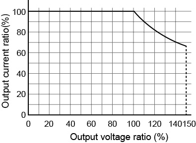
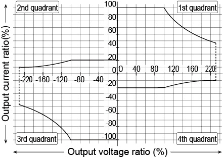
The output voltage ratio is a percentage where 100 % represents an output voltage of 100 V (output L range) or 200 V (output H range) in AC mode or DC mode. The output current ratio is a percentage where 100 % represents the maximum rated output current in AC mode or DC mode.
The instantaneous peak current ratio is the instantaneous peak current expressed as a percentage of the rated maximum output current.
The rated output current in AC mode depends on the output conditions (output voltage, load power factor, output frequency). The rated output current under given output conditions is the value obtained by converting the smaller of the two values: the product of the output current ratios derived from fig. 1 (output voltage) and fig. 3 (load power factor) and the output current ratio derived from fig. 4 (output frequency).
■ Fig.1 Output voltage ratio versus output current ratio (AC mode)
■ Fig.2 Output voltage ratio versus rated output current ratio (DC mode)
■ Fig.3 Load power factor versus output current ratio
■ Fig.4 Output frequency versus output current ratio
■ Fig.5 Instantaneous output voltage versus instantenous peak current ratio (AC mode L range, excluding three-phase three-wire output)
■ Fig.6 Instantaneous output voltage versus instantenous peak current ratio (AC mode H range, excluding three-phase three-wire output)
![]() AC power supply PCR-LE2 series
AC power supply PCR-LE2 series
Specifications