AC power supply PCR-LE2 series
Appendix
Maximum peak current (AC mode)
Maximum instantaneous current (DC mode/ AC+DC mode)
Instantaneous peak currenst (AC mode)
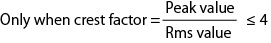
Instantaneous peak current ratio
Output voltage waveform distortion ratio
Output voltage response speedCapacitor-input rectifier load (circuit)
This is the maximum output power capacity (in VA) that can be supplied continuously in the following ranges. For example, this is 6 kVA on the PCR6000LE2.
In DC mode, this value is 70 % of the value in AC mode.
|
|
AC mode |
DC mode |
|
|
Output voltage |
Output L range |
100 V to 150 V |
100 V to 212 V |
|
Output H range |
200 V to 300 V |
200 V to 424 V |
|
|
Load power factor |
0.8 to 1.0 |
NA |
|
|
Output frequency |
0 Hz to 999.9 Hz |
NA |
|
This is the maximum continuous output current (rms value). (Unit: A.)
The rated output current requires derating (reduction), which is performed according to the output conditions (output voltage, frequency, and load power factor).
This is the maximum rms output current (in A) that can be supplied continuously in the following ranges. For example, this is 6 kVA on the PCR6000LE2.
In DC mode, this value is 70 % of the value in AC mode.
|
|
AC mode |
DC mode |
|
|
Output voltage |
Output L range |
100 V |
100 V |
|
Output H range |
200 V |
200 V |
|
|
Load power factor |
0.8 to 1.0 |
NA |
|
|
Output frequency |
40 Hz to 999.9 Hz |
NA |
|

*: See “Output voltage ratio”,Output L range is 100 V, and output H range 200 V.
Maximum peak current (AC mode)
This is the maximum continuous output current (peak value in Apeak) that the PCR-LE Series can supply when using a capacitor-input rectifier load.
Maximum peak current = rated maximum output current (rms) × 4
Output voltage: 100 V to 150 V (for output L range)
200 V to 300 V (for output H range)
Output frequency: 40 Hz to 999.9 Hz
Maximum instantaneous current (DC mode/ AC+DC mode)
This is the maximum instantaneous output current (peak current in Apeak) that can be supplied to the load in DC mode or AC+DC mode.
Maximum instantaneous current = Rated maximum output current × 3.6
Instantaneous peak currenst (AC mode)
This is the maximum instantaneous output current (peak current in Apeak) that can be supplied to the load in AC mode.
This depends on the output range, voltage setting, and instantaneous output voltage.
The instantaneous peak current near the peak value of the instantaneous output voltage is four times the rated maximum output current (maximum peak current), but it decreases in accordance with the reduction in the absolute value of the instantaneous output voltage.
Figs. 10 and 11 show “Instantaneous output voltage versus instantaneous peak current ratio” for the representative voltage settings of each range.
Instantaneous peak current ratio
This is the instantaneous peak current as a percentage where the rated maximum output current is 100 %.
This is the output current as a percentage where the rated maximum output current is 100 %.
This is the output voltage as a percentage where 100 V for the output L range or 200 V for the output H range is 100 %.
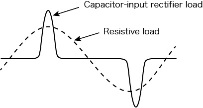
Output voltage waveform distortion ratio
This is the total harmonic distortion (in %) of the output voltage waveform when the output voltage is between 80 V and 150 V (for output L range) or between 160 V and 300 V (for output H range) and the load power factor is 1.
This is the time duration defined by the output voltage change exceeding 10 % of the total change and then returning back to 10 % or less of the total change when the output current ratio has changed from 0 % to 100 % under the following conditions: the output voltage is 100 V (for output L range) or 200 V (for output H range) and the load power factor is 1 (in AC mode). (The unit is µs.)
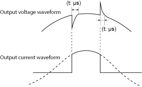
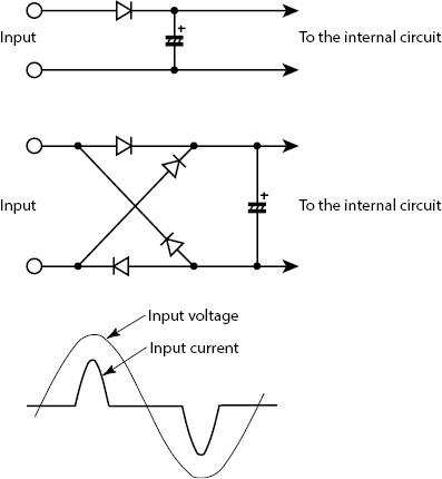
Capacitor-input rectifier load (circuit)
This is a load whose rectifier circuit part is constructed as shown below. The rectifier circuit is used to convert the input AC voltage into the DC voltage that the device needs to operate.
The peak input current is normally approximately two to four times the rms value. The conduction angle (the period that the current is flowing for) centered on the peak output voltage (phase angle of 90 deg or 270 deg) is approximately 20 deg to 90 deg.
"Derating" means "reducing." In general, this refers to using a device at reduced maximum rated values (such as the voltage and the current) depending on the ambient conditions (such as the temperature and load).
This refers to situations in which the voltage in a commercial power line drops momentarily due to the effects of lightning and other similar phenomena.
Generally, these voltage drops last for several tens of milliseconds to several hundreds of milliseconds, and the voltage drops by 20 % to 80 %.
![]() AC power supply PCR-LE2 series
AC power supply PCR-LE2 series
Appendix