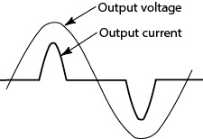
AC power supply PCR-LE2 series
Appendix
Rated output current in AC mod
Rated output current in DC/AC+DC mode
The rated current is automatically derated (reduced) depending on the output conditions (output voltage, frequency, and load power factor).
Output voltage ratio:
A percentage where 100 % represents an output voltage of 100 V (output L range) or 200 V (output H range).
Output current ratio:
A percentage where 100 % represents the rated maximum output current.
Instantaneous peak current ratio:
A percentage where 100 % represents the rated maximum output current.
Rated maximum output current:
Single-phase output
|
|
PCR 6000LE2 |
PCR 9000LE2 |
PCR 12000LE2 |
PCR 18000LE2 |
PCR 27000LE2 |
|
L range |
60 A |
90 A |
120 A |
180 A, |
270 A |
|
H range |
30 A |
45 A |
60 A |
90 A |
135 A |
Single-phase three-wire output/ Three-phase output
|
|
PCR 6000LE2 |
PCR 9000LE2 |
PCR 12000LE2 |
PCR 18000LE2 |
PCR 27000LE2 |
|
L range |
20 A |
30 A |
40 A |
60 A, |
90 A |
|
H range |
10 A |
15 A |
20 A |
30 A |
45 A |
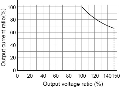
• Fig.7 Output voltage ratio versus output current ratio (AC mode)
Output current ratio [%] when the output voltage setting (ACvolt) is between 0 V and 100 V (L range) or between 0 V and 200 V (H range): 100
Output current ratio [%] when the output voltage setting (ACvolt) is 100 V or higher (L range) or 200 V or higher (H range): 100/ Output voltage ratio ×100
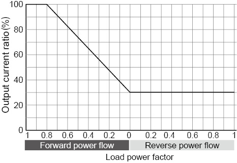
• Fig.8 Load power factor versus output current ratio
Output current ratio [%] when the load power factor is greater than 0.8: 100
Output current ratio [%] for forward power flow when the load power factor is less than or equal to 0.8:
30 + load power factor × 70/0.8
Output current ratio [%] for reverse power flow: 30
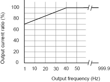
• Fig.9 Output frequency versus output current ratio
Output current ratio [%] when the output frequency (Freq) is less than 40 Hz: 70+ output frequency×30/ 40
Output current ratio [%] when the output frequency (Freq) is greater than or equal to 40 Hz: 100
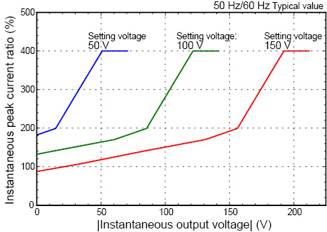
• Fig.10 Instantaneous output voltage ratio versus instantaneous peak current ratio (AC mode L range, excluding three-phase three-wire output)
The instantaneous output voltage is the instantaneous value of the output voltage waveform.
This shows the instantaneous peak current ratio in relation to the instantaneous output voltage when the output voltage is set to 50 V, 100 V, and 150 V.
For example, the instantaneous peak current that can be supplied when the setting voltage is 100 V is 160 % of the rated current (rms) when the instantaneous output voltage is 50 V and 280 % of the rated current (rms) when the instantaneous output voltage is 100 V.
During three-phase three-wire output, the instantaneous peak current ratio is limited also by the instantaneous output voltage of other phases.
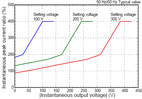
• Fig.11 Instantaneous output voltage ratio versus instantaneous peak current ratio (AC mode H range, excluding three-phase three-wire output)
The instantaneous output voltage is the instantaneous value of the output voltage waveform.
This shows the instantaneous peak current ratio in relation to the instantaneous output voltage when the output voltage is set to 100 V, 200 V, and 300 V.
For example, the instantaneous peak current that can be supplied when the setting voltage is 200 V is 160 % of the rated current (rms) when the instantaneous output voltage is 100 V and 280 % of the rated current (rms) when the instantaneous output voltage is 200 V.
During three-phase three-wire output, the instantaneous peak current ratio is limited also by the instantaneous output voltage of other phases.
How the rated output current is determined on the PCR6000LE2
The rated output current in AC mode depends on the output conditions (output voltage, load power factor, output frequency). The rated output current under given output conditions is the value obtained by converting the smaller of the two values: the product of the output current ratios derived from fig. 7 (output voltage) and fig. 8 (load power factor) and the output current ratio derived from fig. 9 (output frequency).
The full scale of the load level meter of control panel is set to 1.1 times the calculated rated current or the current limit, whichever is less.
Example
If you use the PCR-LE2 Series under conditions that exceed those that produce the rated output currents described below, the protection functions may be activated, which may cause the output voltage to drop, or turn off the output.
Example 1: The output voltage is 80 V (L range), the load power factor is 0.6, and the output frequency is 50 Hz.
From the fig.7, the output current ratio at an output voltage of 80 V is 100 %. - - -(a)
From the fig.8, the output current ratio at a load power factor of 0.6 is 82.5 %. - - - (b)
From the fig.9, the output current ratio at an output frequency of 50 Hz is 100 %. - - - (c)
From (a) and (b), the output current ratio at an output voltage of 80 V and a load power factor of 0.6 is
(a)×(b) = 82.5 % - - - - - - - - - - - - - - - - - - - - - - - - (d)
Because (d) is smaller than (c), the output current ratio is limited by (d), which was calculated as (d). Therefore, the maximum output current ratio is 82.5 %.
On the PCR6000LE2, the rated maximum output current for the output L range is 60 A (Single-phase output), so the rated output current under the above conditions is
60×0.825 = 49.5 A
Example 2: The output voltage is 250 V (H range), the load power factor is 0.4, and the output frequency is 60 Hz.
From the fig.7, the output current ratio at an output voltage of 250 V is 80 %. - - (a)
From the fig.8, the output current ratio at a load power factor of 0.4 is 65 %. - - - (b)
From the fig.9 the output current ratio at an output frequency of 60 Hz is 100 %. - - - (c)
From (a) and (b), the output current ratio at an output voltage of 250 V and a load power factor of 0.4 is
(a)×(b) = 52 % - - - - - - - - - - - - - - - - - - - - - - (d)
Because (d) is smaller than (c), the output current ratio is limited by (d). Therefore, the maximum output current ratio is 78 %.
On the PCR6000LE2, the rated maximum output current for the output H range is 30 A (Single-phase output), so the rated output current under the above conditions is
30×0.52 = 15.6 A
Example 3: The output voltage is 80 V (L range), the load power factor is 0.6, and the output frequency is 10 Hz.
From the fig.7, the output current ratio at an output voltage of 80 V is 100 %. - - (a)
From the fig.8, the output current ratio at a load power factor of 0.6 is 82.5 %. - - - (b)
From the fig.9 the output current ratio at an output frequency of 10 Hz is 77.5 %. - - - (c)
From (a) and (b), the output current ratio at an output voltage of 80 V and a load power factor of 0.6 is
(a)×(b) = 82.5 % - - - - - - - - - - - - - - - - - - - - - - (d)
Because (c) is smaller than (d), the output current ratio is limited by (c). Therefore, the maximum output current ratio is (c) = 77.5 %.
On the PCR6000LE2, the rated maximum output current for the output H range is 30 A (Single-phase output), so the rated output current under the above conditions is
30×0.775 = 46.5 A
How peak current that can be supplied is determined (for single-phase output)
As shown in figs. 10 and 11, “Instantaneous output voltage versus instantaneous peak current ratio,” the peak current supply performance depends on the output range, voltage setting, and instantaneous output voltage.
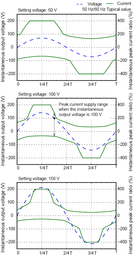
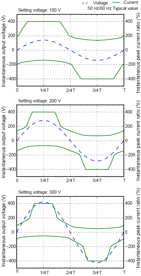
Figs. 12 and 13 show the range in which peak current can be supplied (range between two solid lines) for the voltage waveforms (broken lines) at the representative voltage settings of each range.
The instantaneous peak current near the peak value of the instantaneous output voltage is four times the rated maximum output current (maximum peak current), but it decreases in accordance with the reduction in the absolute value of the instantaneous output voltage. If this range is exceeded, the protection functions of this product may be activated, which may distort the output voltage waveform or turn off the output.
For loads through which inrush current flows, such as transformers, motors, lamps, and capacitor-input rectifier circuits, check the current waveform, and provide adequate margin so that the peak current supply range is not exceeded. In addition, keep the rms value of the output current from exceeding the rated output current or in the case of reverse power flow, 30 % of the rated output current.
• Fig.12 Voltage waveform versus peak current supply range (AC mode L range)
• Fig.13 Voltage waveform versus peak current supply range (AC mode H range)
How peak current that can be supplied is determined (for three-phase output)
Also for three-phase output, the peak current supply performance depends on the output range, voltage setting, and instantaneous output voltage as shown in fig. 10 and fig. 11, “Instantaneous output voltage versus instantaneous peak current ratio.”
If you are using three-phase four-wire output, read “setting voltage” as “setting phase voltage” and “instantaneous output voltage” as “instantaneous value of phase voltage” in fig. 10 and fig. 11.
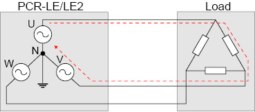
If you are using three-phase three-wire output, because the phase voltages of the two phases are connected in series as shown in the following figure, the instantaneous peak current ratio is limited also by the instantaneous output voltage of the other phase. As such, the instantaneous peak current ratio when the instantaneous output voltage of the other phase is near 0 V may be lower than the rating.
Capacitor-input rectifier loads
For electronic devices that have capacitor-input rectifier circuits in their input, when the output voltage approaches the peak output voltage, a peak current several times greater than the output current rms value flows as the output current.
As shown in figs. 10 to 13, keep the maximum peak current near the peak value of the instantaneous output voltage from exceeding four times the rated maximum output current.

*: Output L range is 100 V, and output H range 200 V.
The output current rms should not exceed the rated output current value calculated with the load power factor set to 1, as explained in "Linear load".
If you use the PCR-LE2 Series with an output current that exceeds the rated output current (peak or rms value) specified above, the protection functions may be activated, which may distort the output voltage waveform or turn off the output.
You can only supply the maximum peak current described above without any distortions when the output voltage (the setting) is fixed. If the output voltage setting is changed suddenly (increased), the voltage and current waveforms may be distorted. Even if you are executing power line abnormality simulations or sequences, distortions may occur in the same manner if the output voltage is changed suddenly. To supply the maximum peak current without distortions, fix the output voltage setting and then turn the output on.
Loads that generate surges
Some loads (for example, fluorescent lights) generate surges when the voltage is applied to the load or when the voltage is changed suddenly. When a surge occurs, the PCR-LE2 Series may malfunction. For this type of load, connect a noise filter to the output cable.
Special loads
If you connect a capacitor directly to the OUTPUT terminal block or the OUTPUT outlets, the output waveform may be distorted. In this situation, connect the capacitor to the load side of the output wiring.
Loads that draw an inrush current
For loads such as those listed below, when the voltage is applied to the load or when the voltage changes suddenly, an inrush current (several times to several tens of times the normal current) flows for several cycles to several tens of cycles of the output frequency.
• Transformer and slide transformer (SLIDAC) loads
When a voltage is applied to a transformer or a slide transformer, an inrush current of up to several hundreds of times the normal current will flow for several cycles depending on the timing that the voltage is applied or the residual magnetization in the transformer.
• Motor and lamp loads
When a voltage is applied to a motor or a lamp, an inrush current of several times to several tens of times the normal current flows for several tens of cycles to several hundreds of cycles.
• Capacitor-input rectifier loads
For electronic devices that have capacitor-input rectifier circuits in their input, if the device does not have an inrush current protection (limitation) circuit, an inrush current of several tens to several hundreds of times the normal current flows for several cycles.
As shown in figs. 10 to 13, for capacitor-input rectifier loads, this product can supply maximum peak current up to four times the rated maximum output current near the peak value of the instantaneous output voltage.
For other loads, this product can supply maximum peak current up to 200 % of the instantaneous peak current ratio for the specified trip time (TRIP TIM) even if the rms value of the output current exceeds the rated output current (varies depending on the current waveform, output voltage, output frequency, and the like).
Examples of the instantaneous peak currents that can be supplied when TRIP is set to ENABLE, the output voltage is set to 100 V, and the output frequency is set to 50 Hz are shown in the following table.
|
Load power factor |
Instantaneous peak current ratio (%)*1 [%] |
|
1.0 |
200 |
|
0.9 |
160 |
|
0.8 |
150 |
|
0.6 |
140 |
|
0.4 |
120 |
|
0.2 |
110 |
*1. The output current ratio as a percentage where 100 % represents the maximum output current of the PCR-LE2 Series
If an inrush current that exceeds the peak currents listed above flows, the protection circuits of the PCR-LE2 Series will be activated, which may distort the output voltage waveform or turn off the output.
Particularly for inductive loads such as transformers and motors, if the protection circuit is activated and the output is turned off, a reverse voltage exceeding the voltage setting may be generated and appear at the output terminals.
The rated DC output current that the PCR-LE2 Series can generate is limited by the output voltage.
Output voltage ratio:
A percentage where 100 % represents an output voltage of 100 V (output L range) or 200 V (output H range).
Output current ratio:
A percentage where 100 % represents the maximum rated current.
Maximum rated current:
Single-phase output
|
|
PCR 6000LE2 |
PCR 9000LE2 |
PCR 12000LE2 |
PCR 18000LE2 |
PCR 27000LE2 |
|
L range |
42 A |
63 A |
84 A |
126 A |
189 A |
|
H range |
21 A |
31.5 A |
42 A |
63 A |
94.5 A |
Singlel-phase three-wire output/ Three-phase output
|
|
PCR 6000LE2 |
PCR 9000LE2 |
PCR 12000LE2 |
PCR 18000LE2 |
PCR 27000LE2 |
|
L range |
14 A |
21 A |
28 A |
42 A |
63 A |
|
H range |
7 A |
10.5 A |
14 A |
21 A |
31.5 A |
• Output voltage ratio versus rated output current in DC mode
Unlike with resistive loads, when a power supply that alternates voltage polarity based on time is applied to an inductive or capacitive load, the current phase becomes lagging or leading to the voltage phase.
If this occurs, there are four possible combinations of the voltage and current polarities. This operation is shown on a graph of voltage (vertical axis) versus current (horizontal axis). The PCR-LE2 Series operates in all four quadrants (and thus the name four-quadrant operation). Power supplies that can operate in this manner are called bipolar power supplies.
Output current ratio [%] of the first quadrant and third quadrant
Output current ratio [%] when the output voltage setting (DCvolt) is between 0 V and 100 V (L range) or between 0 V and 200 V (H range): 100
Output current ratio [%] when the output voltage setting (DCvolt) is 100 V or higher (L range) or 200 V or higher (H range): 100/ Output voltage ratio ×100
Output current ratio [%] of the second quadrant and fourth quadrant
Output current ratio [%] when the output voltage setting (DCvolt) is between 0 V and 100 V (L range) or between 0 V and 200 V (H range): 21
Output current ratio [%] when the output voltage setting (DCvolt) is 100 V or higher (L range) or 200 V or higher (H range): 100/ Output voltage ratio ×21
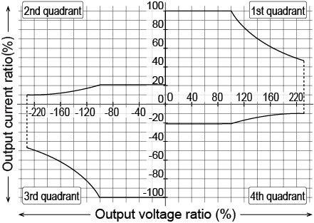
If you use the PCR-LE2 Series with a current that exceeds the rated DC output current, the protection functions will be activated, which may cause the output voltage to drop or turn off the output.
![]() AC power supply PCR-LE2 series
AC power supply PCR-LE2 series
Appendix