AC power supply PCR-LE2 series
Advanced
The output can be controlled using external analog signals by installing the analog signal interface board (EX05-PCR-LE/ EX06-PCR-LE) to the slot3.
For details of installing the board on the PCR-LE, see the setup guide of EX05-PCR-LE/EX06-PCR-LE.
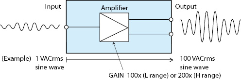
• Amplifying the input waveform (EX05-PCR-LE only)
- Note -
Only single-phase output is valid on the PCR6000LE2 and PCR9000LE2.
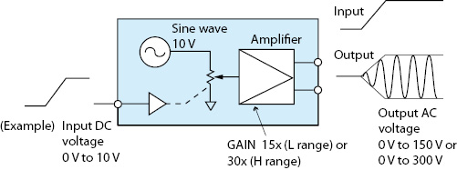
• Varying the voltage of the output AC waveform using DC signals (EX06-PCR-LE only)
• Controlling the PCR-LE2 through external contacts
You can turn the output on and off, execute and stop sequences, clear alarms, and shut down the output.
• Monitoring the operation status
You can monitor the output status, alarm status, busy status, current peak limit status, and overload status.
 CAUTION
You cannot set the voltage limit when the PCR-LE2 is being controlled using external analog signals. Accidentally applying an excessive external voltage may damage the load.
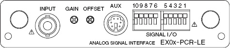
Names and functions of the parts of the analog signal interface board
|
Name |
Description |
|
INPUT |
BNC terminal for applying the external signal Input terminals is electrically isolated from the output terminals of the PCR-LE2. |
|
GAIN |
Variable resistor for fine adjusting the gain (voltage amplification ratio) |
|
OFFSET |
Variable resistor for fine adjusting the offset |
|
AUX |
This is a connector for options. |
|
SIGNAL I/O |
Connector for controlling the PCR-LE2 through external contacts |
You can use the PCR-LE2with EX05-PCR-LE as a power amplifier that simply amplifies the input waveform or use it to add an external signal to the PCR-LE2 Series signal source.
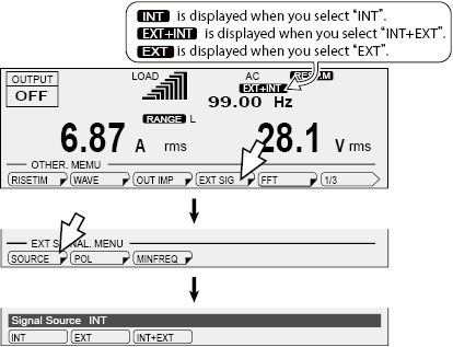
Selecting the signal source
Select which signal source to use to control the PCR-LE2 Series.
• Internal signal source (INT)
Output the PCR-LE2 Series signal source. External signal sources are not used.
• Internal signal source and external signal source (INT+EXT)
Output the sum of the PCR-LE2 Series signal source and an external signal source.
If you select INT+EXT, the PCR-LE2 Series settings will be changed as follows:
Action to perform when the current limit is exceeded: Turn the output off
Internal Vcc: FIXED: (previously set value)
Compensation function: OFF (when soft sensing or regulation adjustment is selected)
Displays the phase voltage (Single-phase three-wire output or three-phase output only)
• External signal source (EXT)
The EX05-PCR-LE amplifies the external signal (0 Vrms to 1.5 Vrms) 100 times when L range is selected and 200 times when H range is selected and outputs the resultant voltage.
If you select EXT, the PCR-LE2 Series settings will be changed as follows:
Action to perform when the current limit is exceeded: Turn the output off
Synchronization function: OFF
Output on/off phase control: FREE
Internal Vcc: FIXED: (previously set value)
Compensation function: OFF (when soft sensing or regulation adjustment is selected)
Soft starts: OFF
Displays the phase voltage (Single-phase three-wire output or three-phase output only)
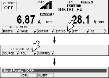
Press OTHERS (SHIFT+MEMORY), EXT SIG(F4) and then SOURCE(F1) to set the signal source.
|
Item |
Title |
Description |
Condition in which the function key cannot be used |
|
INT |
Signal Source |
Use the internal signal. |
Output on |
|
EXT |
Use the external signal. |
||
|
INT+EXT |
Use the internal signal and external signal. |
 CAUTION
Risk of malfunction. If you output DC voltage in AC mode, the protection features will not function properly. If you want to output DC voltage, use the PCR-LE2 Series within 70 % of the rated current, or change the output voltage mode to AC+DC.
Selecting the polarity
Select whether to output a signal whose polarity is the same as or opposite to that of the input signal.
Press OTHERS (SHIFT+MEMORY), EXT SIG(F4) and then POL(F2) to set the polarity.
During single-phase, three-wire output and three-phase output, press OTHERS (SHIFT+MEMORY), EXT SIG(F4), and then press the key that corresponds to the phase that you want to set, and then POL(F2) to set the polarity.
|
Item |
Title |
Description |
|
NORM |
Signal Polarity U Signal Polarity*1 V Signal Polarity*1 W Signal Polarity*2 |
Output a signal whose polarity is the same as the input signal. |
|
INVERT |
Output a signal whose polarity is opposite to that of the input signal. |
*1. Single-phase three-wire output and three-phase output only
*2. Three-phase output only
Setting the aperture time (only when using EXT)
To use an external signal source (EXT), set the aperture time.
If the aperture time is not set, the voltage and current that are being output may be different from what are displayed on the panel.
The aperture time setting was added in firmware version 5.00. As a result, the function for setting the estimated minimum frequency that was available in firmware version 4.99 and earlier is no longer available.
Setting the internal Vcc
If you set the signal source to EXT or EXT+INT, the internal Vcc is changed to a fixed value. Set the Internal Vcc value to the voltage that you want to output (peak value) + 10 V.
If the internal Vcc is set to a value greater than the actual output voltage, the protection function may be activated. If the internal Vcc is set to a value less than the actual output voltage, a few hundred milliseconds of response delay will occur.
Outputting the signal
After you set the signal source, polarity, and the estimated minimum frequency (EXT only), apply an external signal to the INPUT terminal.
|
1 |
Check that the POWER switch is turned off. |
|
2 |
Connect an external signal (generator) to the INPUT terminal. |
|
3 |
Turn the POWER switch on. |
|
4 |
Press the RANGE (SHIFT+8) key to set the voltage range (L/H) |
|
5 |
Apply an external signal to the INPUT terminal. |
|
6 |
Turn the OUTPUT on. |
Fine adjusting the offset
You can fine adjust the offset by turning the OFFSET variable resistor using the adjustment screwdriver. Adjust the offset so that the output voltage is as close to 0 Vdc as possible with the input terminal shorted.
Fine adjusting the gain
You can fine adjust the gain by turning the GAIN variable resistor using the adjustment screwdriver. Adjust the gain so that the output voltage is 150 Vac (L range) when 1.5 Vac is applied to the input terminal.
Functional limitations
If you use an external signal, you will not be able to use the following functions, in addition to the settings that were changed when you selected the signal source.
• When the internal signal source plus the external signal source are used
Harmonic current analysis function
• When the external signal source is used
Setting the output voltage, voltage limit
Setting the frequency, frequency limit
Using memory
Special waveforms
Harmonic current analysis function
Power line abnormality simulations
Sequence function
Phase difference (Single-phase three-wire output or three-phase output only)
When AC mode or AC+DC mode is selected, the PCR-LE2 with EX06-PCR-LE outputs AC voltage ranging from 0 V to 150 V (when L range is selected) or 0 V to 300 V (when H range is selected) with respect to a DC signal input ranging from 0 V to 10 V.
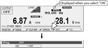
Selecting the signal source
Select whether to control the output AC voltage using an external signal.
Press OTHERS (SHIFT+MEMORY) and then, VPROG(F4) to set the signal source.
|
Item |
Title |
Description |
Condition in which the function key cannot be used |
|
ON |
VProg |
Control the AC voltage using an external signal |
OUTPUT on Soft start: ON |
|
OFF |
Do not control the AC voltage using an external signal |
Outputting the signal
After you set the signal source, apply an external signal to the INPUT terminal.
|
1 |
Check that the POWER switch is turned off. |
|
2 |
Connect an external signal (generator) to the INPUT terminal. |
|
3 |
Turn the POWER switch on. |
|
4 |
Press the OPR MODE > ACDC(F2) to set the output mode (AC/ AC+DC). |
|
5 |
Press the RANGE (SHIFT+8) key to set the voltage range (L/H). |
|
6 |
Press F > FREQ(F1) to set the frequency (1.0 Hz to 999.9 Hz). |
|
7 |
Apply an external signal to the INPUT terminal. |
|
8 |
Turn the OUTPUT on. |
Fine adjusting the offset and the gain
You can fine adjust the offset by turning the OFFSET variable resistor using the adjustment screwdriver. You can fine adjust the gain by turning the GAIN variable resistor using the adjustment screwdriver.
|
1 |
Apply 1 Vdc to the INPUT terminal. |
|
2 |
Turn the OUTPUT on. |
|
3 |
Using an adjustment screwdriver, adjust the OFFSET variable resistor so that the output voltage is at 15 Vdc (L range). |
|
4 |
Apply 10 Vdc to the INPUT terminal. |
|
5 |
Using an adjustment screwdriver, adjust the GAIN variable resistor so that the output voltage is at 150 Vdc (L range). |
|
6 |
Apply 1 Vdc to the INPUT terminal, and check that the output voltage is 15 Vdc (L range). If it is not, repeat steps 1 to 5 until the output voltage is 15 Vdc (L range). When you adjust either the offset or the gain, the other value that you adjusted before may shift. Be sure to double-check both values. |
|
7 |
Turn the OUTPUT off. |
Functional limitations
If an external signal is used, you will not be able to use the following functions.
Setting the output AC voltage
Soft starts
Power line abnormality simulations
Sequence function
 WARNING
Risk of electric shock. Never attempt to connect wires to the SIGNAL I/O connector while the POWER switch turned on.
Pin arrangement and connection
To control the PCR-LE2 Series through external contacts, use pins 6 to 10 of the SIGNAL I/O connector.
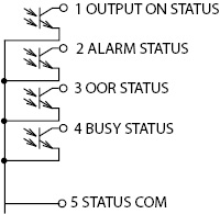
To monitor the operation status of the PCR-LE2 Series, use pins 1 to 5 of the SIGNAL I/O connector.
Remove the covering from each wire over a distance of 9 mm to 10 mm (10 mm is recommended).

|
Pin |
Signal Name |
Description |
|
1 |
OUTPUT ON STATUS |
Output on status monitor |
|
2 |
ALARM STATUS |
Alarm status monitor |
|
3 |
OOR STATUS |
Current peak limit status and Overload status monitor |
|
4 |
BUSY STATUS |
Busy status monitor |
|
5 |
STATUS COM |
Output signal common |
|
6 |
OUTPUT CONTROL |
Output on/ off control |
|
7 |
SEQ RUN |
Sequence execute/ stop |
|
8 |
ALARM CLR |
Alarm clear |
|
9 |
SHUT DOWN |
Shut down the output |
|
10 |
COM |
Input signal common |
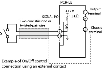
Controlling the PCR-LE2 through external contacts
Wiring
To minimize the influence of noise on the output, use a two-core shielded wire or a twisted-pair wire to connect the control terminals and the external contact. Make the wires as short as possible. Susceptibility to the effects of noise increases as the wires get longer. When wires are long, proper operation may be hindered even if a cable with anti-noise measures is used.
The release voltage across pins is approx. 12 V maximum, and the short circuit current is approx. 8.5 mA maximum. (The internal circuit is pulled up to 12 V through 1.3 kΩ.)
Use parts with a contact rating of 12 Vdc and 8.5 mA for the external contact.
High level input voltage (HIGH): 11 V to 12 V, or open circuit
Low level input voltage (LOW): 0 V to 1 V
When using a shielded cable, connect the shield to the chassis.
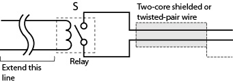
For long-distance wiring
When wiring over a great distance, use a small relay and extend the coil side of the relay.
Controlling the Output On/ Off
Use pins 6 to 10 of the SIGNAL I/O connector to turn the output on and off through external contacts.
If multiple units are used under floating conditions and a single external contact is used to turn on/off the output, isolate the signal to each unit such as by using a relay on the external contact signal.
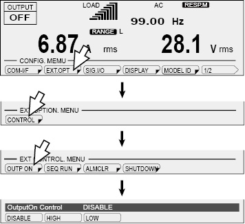
Press CONFIG (SHIFT+OPR MODE), EXT.OPT(F2), CONTROL(F1) and then, OUTP ON(F1) to set the external control logic of output on/off.
|
Item |
Title |
Description |
|
DISABLE |
OutputOn Control |
Do not turn the output on and off through external contacts. |
|
HIGH |
Turn the output on with a high signal. |
|
|
LOW |
Turn the output on with a low signal. |
If the output is set to off using an external contact, the OUTPUT key on the front panel is invalid. If you do not want to control the output through external contacts, set the output control logic to DISABLE.
The figure below shows an example of output on/off control when a high level signal turns the output on.
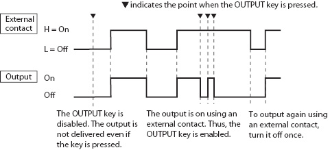
When a sequence is running, the output on/off control through external contacts is invalid.
Controlling the Sequence Execute/Stop
Use pins 7 to 10 of the SIGNAL I/O connector to turn the sequence execute and stop through external contacts.
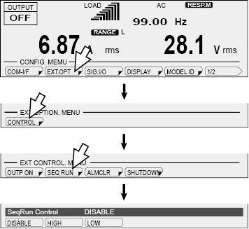
Press CONFIG (SHIFT+OPR MODE), EXT.OPT(F2), CONTROL(F1) and then, SEQ RUN(F2) to set the external control logic of sequence run/stop.
|
Item |
Title |
Description |
|
DISABLE |
SeqRun Control |
Do not execute/stop the sequence through external contacts. |
|
HIGH |
Execute the sequence with a high signal. |
|
|
LOW |
Run the sequence with a low signal. |
When a sequence is stopped through external contacts, RUN (F1) on the front panel is invalid. If you do not want to control the sequence through external contacts, set the output control logic to DISABLE.
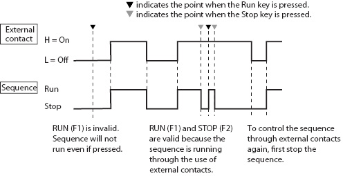
The figure below shows an example of sequence execute/stop control when a high level signal execute the sequence.
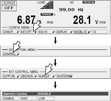
Use pins 8 and 10 of the SIGNAL I/O connector to clear alarms through external contacts.
Press CONFIG (SHIFT+OPR MODE), EXT.OPT(F2), CONTROL(F1) and then, ALMCLR(F3) to set the external control logic of alarm clear.
|
Item |
Title |
Description |
|
DISABLE |
AlarmClr Control |
Do not clear alarms through external contacts |
|
HIGH |
Alarm clear with a high signal. |
|
|
LOW |
Alarm clear with a low signal. |
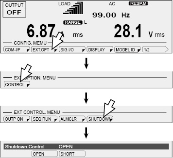
Use pins 9 and 10 of the SIGNAL I/O connector to shut down the output through external contacts. This takes precedence over the feature that turns the output on and off through external contacts.
When the output is shut down, “TRBL-19 EXT.SHUTDOWN” appears on the panel.
Press CONFIG (SHIFT+OPR MODE), EXT.OPT(F2), CONTROL(F1) and then, SHUTDOWN(F4) to set the external control logic of shutdown.
|
Item |
Title |
Description |
|
OPEN |
Shutdown Control |
Turn output off with open circuit (input voltage: 11 V to 12V). |
|
SHORT |
Turn output off with short circuit (input voltage: 0 V to 1 V). |
Recovery
Turn the POWER switch off.
If the external control logic is OPEN, short pins 9 and 10, and turn the POWER switch on.
If the external control logic is SHORT, open pins 9 and 10, and turn the POWER switch on.
You can externally monitor the following operation status of the PCR-LE2.
• Output (OUTPUT ON STATUS)
Use pins 1 and 5 of the SIGNAL I/O connector.
The signal turns on when the output is on.
• Alarm occurrence (ALARM STATUS)
Use pins 2 and 5 of the SIGNAL I/O connector.
The signal turns on when an alarm or trouble occurs.
• Current peak limit and overload (OOR STATUS)
Use pins 3 and 5 of the SIGNAL I/O connector.
The signal turns on when the current limit is exceeded (OVERLOAD indication) and when current peak is being limited (IPKLIM indication).
• Busy (BUSY STATUS)
Use pins 4 and 5 of the SIGNAL I/O connector.
The signal turns on when the output cannot be turned on (busy status).
For a few seconds when the sleep function is disabled
For approx. 0.6 seconds when the output voltage range is switched
For approx. 120 seconds when the current limit is exceeded
For approx. 120 seconds when the internal semiconductor protection is activated
For a few seconds when the output phase is switched
For a few seconds when the output method for single-phase three-wire output is switched
The output signals are open collector outputs of photocouplers (30 Vdc, 8 mA); they are insulated from the internal circuits of the PCR-LE2.
Maximum voltage: 30 V
Maximum current (Sink): 8 mA
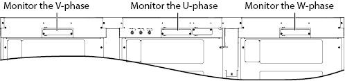
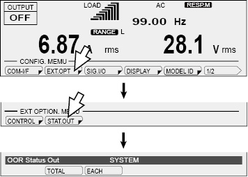
Selecting the phase to monitor (PCR27000LE2 only)
If you want apply current peak limit and overload monitoring (OOR STATUS) during single-phase three-wire output or three-phase output, you can select whether to monitor the entire system or each phase. To monitor each phase, an analog signal interface board must be installed for the phase that you want to monitor.
Press CONFIG (SHIFT+OPR MODE), EXT.OPT (F2), STAT.OUT (F2) and then, LMT STAT (F1) to select the phase that you want to monitor.
|
Item |
Title |
Description |
|
TOTAL |
OOR Status Out |
Monitor the entire system and output the status. |
|
EACH |
Monitor the phase for which the board is installed and output the status. |
![]() AC power supply PCR-LE2 series
AC power supply PCR-LE2 series
Advanced