
PAT160-150TM/TMX (200 V input) specification
 Open PDF file(108 Kb)
Unless specified otherwise, the specifications are for the following settings and conditions.
- The load is a pure resistance.
- The warm-up time is 30 minutes (with current flowing).
- After warm-up is complete, the PAT-TM/TMX series must be calibrated correctly according to the procedures given in the operation manual in a 23 °C ± 5 °C environment.
- TYP (typical) values do not guarantee the performance.
- rtg: Indicates the rated output.
- rdng: Indicates the reading.
- Rated load and no load are defined as follows.
During constant voltage operation (set the output current at the rated voltage output greater than equal to the rated output current)- Rated load: Refers to a load with a resistance that makes the current that flows when the rated output voltage is applied to be 95 % to 100 % of the rated output current at the rated output voltage.
- No load: Refers to a load through which no output current flows or an open output terminal condition with no load connected.
During constant current operation (set the output voltage at the rated output current greater than equal to the rated output voltage)- Rated load: Refers to a load with a resistance that makes the voltage drop when the rated output current is supplied to be 95 % to 100 % of the maximum output voltage at the rated output current.
The output voltage of the PAT-TM/TMX series including the voltage drop in the load cable must not exceed the maximum output voltage at the rated output current. - No load: Refers to a load with a resistance that makes the voltage drop when the rated output current is supplied to be 10 % of the maximum output voltage or 1 V, whichever is greater, at the rated output current.
AC input
| Nominal input rating | 200 V to 240 V, 50 Hz to 60 Hz, three-phase |
| Input voltage range | 180 V to 250 V |
| Input frequency range | 47 Hz to 63 Hz |
| Current (MAX) *1 | 96 A |
| Inrush current (MAX) *2 | 300 Apeak |
| Wattage (MAX) *1 | 30 kVA |
| Power factor (TYP) *3 | 0.95 |
| Efficiency (MIN) *3 | 85 % |
*1. At the rated load.
*2. Excluding the element of charging current flown into the capacitor of the internal circuit of the EMC filter approximately within 1 ms right after turning on the breaker switch of the PAT-TMX series or turning on the switch of the switch board while the POWER switch is turned on of each power supply unit of the PAT-TM series.
*3. Input voltage of 200 Vac, at the rated load.
Output
| Rating | Output power | 24.00 kW | |
| Output voltage | 160.0 V | ||
| Output current | 150.0 A | ||
| Voltage | Maximum preset voltage (TYP) | 105 % of rtg *1 | |
| Setting accuracy | ± (0.2 % of rtg +50 mV) *2 | ||
| Rise time (MAX) | 100 ms (No load) *3 | ||
| Fall time (MAX) | 2000 ms (No load) *4 | ||
| Current | Maximum preset voltage (TYP) | 105 % of rtg *1 | |
| Setting accuracy | ± (1.5 % of rtg +500 mA) *2 | ||
*1. The maximum preset voltage and current are used to determine constant voltage or constant current operation when the activation point of the constant voltage or constant current operation is set to the rated output voltage or current. It does not guarantee power supply to the load exceeding the rated output voltage or current.
To establish a constant voltage operation at the activation point (rated output voltage or current), set the output current (I Set) so that rated output current < I Set ≤ maximum preset current. Likewise, to establish constant current operation, set the output voltage (V Set) so that rate output voltage < V Set ≤ maximum preset voltage.
*2. The difference between the actual output voltage or output current and the preset value under constant voltage or constant current operation.
*3. The time it takes for the output voltage to rise from 10 % to 90 % of the rating when the output is turned on.
*4. The time it takes for the output voltage to fall from 90 % to 10 % of the rating when the output is turned off.
Display function
| Voltmeter | Maximum display | 999.9 (fixed decimal point) | |
| Display accuracy | ± (0.2 % of rdng +5 digits) at 23 °C ± 5 °C | ||
| Ammeter | Maximum display | 999.9 (fixed decimal point) | |
| Display accuracy | ± (0.6 % of rdng +10 digits) at 23 °C ± 5 °C | ||
| Operation display | OUTPUT ON/OFF | ON: OUTPUT LED illuminates (Green LED) OFF: OUTPUT LED turns off |
|
| ALM operation | ALARM LED illuminates (Red LED) *1 | ||
| CV operation | CV LED illuminates (Green LED) | ||
| CC operation | CC LED illuminates (Red LED) | ||
| RMT operation | RMT LED illuminates during remote control (Green LED) | ||
| EXT operation | EXT LED illuminates during external control (Green LED) | ||
| LOCK operation | LOCK LED illuminates when the keys are locked (Green LED) | ||
*1. Illuminates when the overvoltage protection (OVP), overcurrent protection (OCP), overheat protection (OHP), input open-phase protection (PHASE), fan failure protection (FAN), incorrect sensing connection protection (SENSE), overheat protection of the bleeder circuit (BOHP) and so on are activated.
Illuminates even when the breaker trips (even when the POWER switch is turned off). In this case, the LED illuminates for approximately 10 to 15 seconds.
Protection functions
| Overvoltage protection (OVP) | Turns off the output or trips the breaker (turns the POWER switch off). ALARM LED illuminates.*1 |
|
| Selectable range | 10 % to 111.5 % of the rated output voltage | |
| Setting accuracy | ± 2 % of rtg | |
| Overcurrent protection (OCP) | Turns off the output or trips the breaker (turns the POWER switch off). ALARM LED illuminates.*1 |
|
| Selectable range | 10 % to 111.5 % of the rated output current | |
| Setting accuracy | ± 3 % of rtg | |
| Overheat protection (OHP) | Turns the output off. ALARM LED illuminates. | |
| Input open-phase protection (PHASE) | Turns the output off. ALARM LED illuminates. | |
| Fan failure protection (FAN) | Turns the output off. ALARM LED illuminates. | |
| Incorrect sensing connection protection (SENSE) | Turns the output off. ALARM LED illuminates. | |
| Overheat protection of the bleeder circuit (BOHP) | Turns the output off. ALARM LED illuminates. | |
| Shut down (SD) | Turns off the output or trips the breaker (turns the POWER switch off). ALARM LED illuminates.*1 |
|
*1. Illuminates even when the breaker trips (even when the POWER switch is turned off). In this case, the LED illuminates for approximately 10 to 15 seconds.
Output signals
| Monitor signal output*1 | VMON (Voltage) | At rated voltage output | 10.00 V ± 0.25 V |
| At 0 V output | 0.00 V ± 0.25 V | ||
| IMON (Current) | At rated current output | 10.00 V ± 0.25 V | |
| At 0 A output | 0.00 V ± 0.25 V | ||
| Status signal output *1, *2 | OUTON STATUS | Turns on when the output is on. | |
| CV STATUS | Turns on during CV operation. | ||
| CC STATUS | Turns on during CC operation. | ||
| ALM STATUS | Turns on when an alarm (OVP, OCP, OHP, BOHP, input open-phase protection, fan failure protection, incorrect sensing connection protection, or shutdown) is detected. | ||
| PWR OFF STATUS | Stays on for approximately 10 to 15 seconds after the POWER switch turns off. | ||
| PWR ON STATUS | Turns on when the POWER switch is on. | ||
*1. J1 connector on the rear panel.
*2. Photocoupler open collector output, maximum voltage 30 V, maximum current (sink) 8 mA, insulated from the output and control circuits, and status signals are not mutually insulated.
Control functions
| External control*1 | EXT-V CV CONT *2 *3 (CV external voltage control) |
0 % to 100 % of the rated output voltage in the range of 0 V to 10 V. |
| EXT-V (FAST) CV CONT *2 *3 (CV external voltage control FAST) |
0 % to 100 % of the rated output voltage in the range of 0 V to 10 V. | |
| EXT-R CV CONT *2 (CV external resistance control) |
0 % to 100 % of the rated output voltage in the range of 0 kΩ to 10 kΩ. | |
| EXT-R (FAIL SAFE) CV CONT *2 (CV external resistance control FAIL SAFE) |
100 % to 0 % of the rated output voltage in the range of 0 kΩ to 10 kΩ. | |
| EXT-V CC CONT *2 *3 (CC external voltage control) |
0 % to 100 % of the rated output current in the range of 0 V to 10 V. | |
| EXT-V (FAST) CC CONT *2 *3 (CC external voltage control FAST) |
0 % to 100 % of the rated output current in the range of 0 V to 10 V. | |
| EXT-R CC CONT *2 (CC external resistance control) |
0 % to 100 % of the rated output current in the range of 0 kΩ to 10 kΩ. | |
| EXT-R (FAIL SAFE) CC CONT *2 (CC external resistance control FAIL SAFE) |
100 % to 0 % of the rated output current in the range of 0 kΩ to 10 kΩ. | |
| OUTPUT ON/OFF CONT*4 | Output on with a low TTL level signal/output on with a high TTL level signal. | |
| SHUT DOWN*5 | POWER switch off with a low TTL level signal. |
*1. J1 connector on the rear panel.
*2. Set EXT-V, EXT-V (FAST), EXT-R, and EXT-R (FAIL SAFE) in the CONFIG settings. The selected function is enabled.
*3. The input impedance EXT-V CV CONT, EXT-V (FAST) CV CONT and EXT-V CC CONT, EXT-V (FAST) CC CONT is approximately 100 kΩ.
The setting accuracy is ±5 % of the rated output voltage or ±5 % of the maximum output current.
*4. Set the logic low/high using CONFIG settings.
*5. The output turns off even if the breaker trip setting of the CONFIG parameter is set so that the POWER switch does not turn off.
Interface
| Common specifications | Software protocol | IEEE Std 488.2-1992 |
| Command language | Complies with the SCPI Specification 1999.0 specifications. | |
| RS232C | Hardware | Complies with EIA232D. |
| D-SUB 9-pin connector (male) *1 | ||
| Baud rate: 1200, 2400, 4800, 9600, 19200, and 38400 bps | ||
| Data length: 7 bits or 8 bits. Stop bit: 1 bit or 2 bits. No parity. | ||
| Flow control X-Flow or none. | ||
| Program message terminator | LF during reception, CR/LF during transmission. | |
| GPIB*2 | Hardware | Complies with IEEE Std 488.1-1987. |
| SH1, AH1, T6, L4, SR1, RL1, PP0, DC1, DT1, C0, and E1. | ||
| 24 pin connector (receptacle) | ||
| Program message terminator | LF or EOI during reception, LF+EOI during transmission. | |
| Primary address | 1 to 30 | |
| USB*2 | Hardware | Complies with USB 2.0. Data rate: 12 Mbps (full speed). |
| Socket B type | ||
| Program message terminator | LF or EOM during reception, LF+EOM during transmission. | |
| Device class | Complies with the USBTMC-USB488 device class specifications. | |
| LAN*2 | Hardware | IEEE 802.3 100Base-TX/10Base-T Ethernet Complies with the LXI Class C, Specification 1.2. |
| IPv4, RJ-45 connector *3 | ||
| Communications protocol | VXI-11 | |
| Program message terminator | LF or END during reception, LF+END during transmission. |
*1. Use a cross cable (null modem cable).
*2. Factory option.
*3. Category 5, use a straight cable.
General specifications
| Weight | Approx. 120 kg (264.55 lb) (PAT-TM: with no breaker) Approx. 130 kg (286.60 lb) (PAT-TMX: with breaker) |
|
| Dimensions | See the outline drawing | |
| Environmental conditions | Operating conditions | Indoor use, Overvoltage Category II |
| Operating temperature | 0 °C to +40 °C (32 °F to +104 °F) | |
| Operating humidity | 20 %rh to 85 %rh (no condensation) | |
| Storage temperature | -25 °C to +70 °C (-13 °F to +158 °F) | |
| Storage humidity | 90 %rh or less (no condensation) | |
| Altitude | Up to 2000 m | |
| Cooling system | Forced air cooling using a fan. (With fan control) | |
| Grounding polarity | Negative grounding or positive grounding possible. | |
| Isolation voltage | ± 500 Vmax | |
| Withstand voltage | Across the input terminals and chassis | No abnormalities at 1500 Vac, 54 mA for 1 minute. |
| Across the input terminals and the output terminals | No abnormalities at 1500 Vac, 54 mA for 1 minute. | |
| Across the output terminals and chassis | No abnormalities at 500 Vdc for 1 minute. | |
| Insulation resistance | Across the input terminals and chassis | 500 Vdc, 30 MΩ or more. (at 70 %rh or less) |
| Across the input terminals and the output terminals | 500 Vdc, 30 MΩ or more. (at 70 %rh or less) | |
| Across the output terminals and chassis | 500 Vdc, 30 MΩ or more. (at 70 %rh or less) | |
| Accessories | Output terminal bolt set | 4 sets (M10 × 30 mm bolts, nuts, and spring washers) |
| Heavy object warning label | 1 pc. | |
| J1/J2 connector kit | 1 set (2 sets of protection covers, 2 sokets, and 30 pins) | |
| Chassis connection wire | 1 set (with screws) | |
| Quick Reference (base model) | 1 pc. (english), 1 pc. (japanese) | |
| Setup Guide | 1 copy | |
| Safety Information | 1 copy | |
| CD-ROM | 1 pc. | |
Dimensions
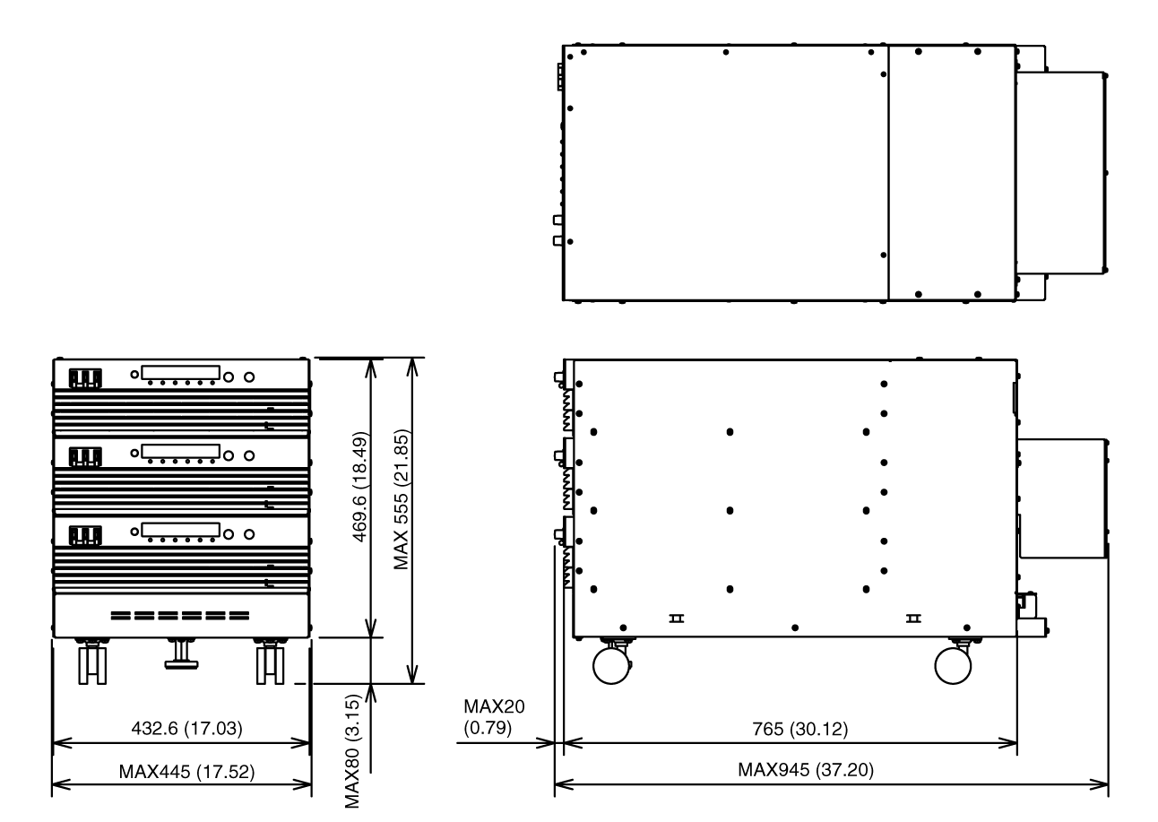
Unit: mm (inch)
PAT-TM Series 24 kW System Outline Drawing
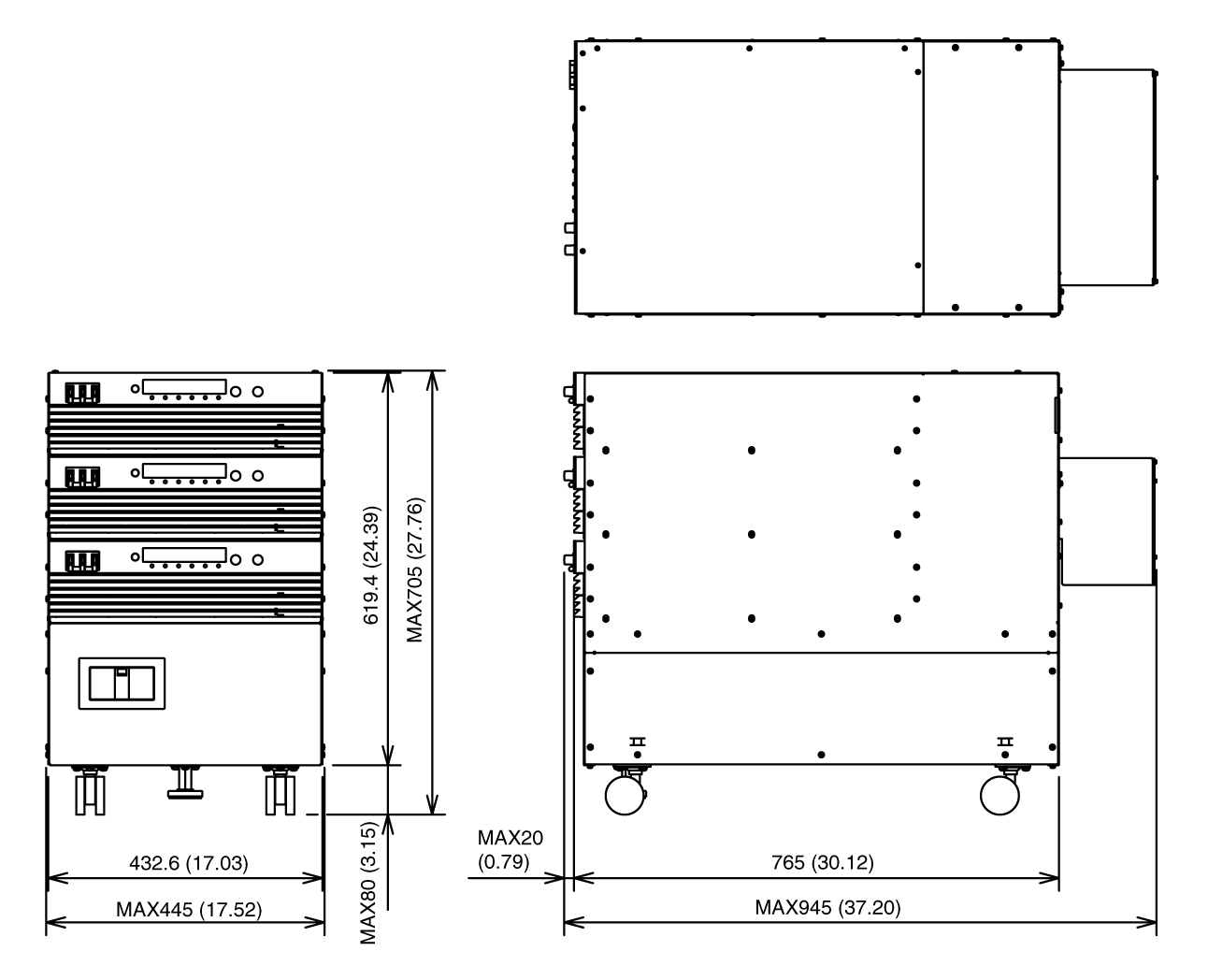
Unit: mm (inch)
PAT-TMX Series 24 kW System Outline Drawing