AC power supply PCR-M series
Operation
The output can be controlled using external analog signals by installing the analog interface board to the option slot. The analog interface board cannot be used together with the GPIB interface or USB interface.
There are two available modes: EXT-AC mode in which the voltage of the output AC waveform (sine wave) is varied according to the input DC signal and EXT-DC mode in which the input waveform is simplify amplified and output.
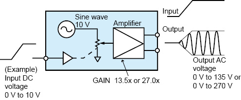
EXT-AC mode
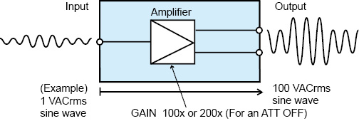
EXT-DC mode
 CAUTION
You cannot set the voltage limit when the PCR-M is being controlled using external analog signals. Accidentally applying an excessive external voltage may damage the load.
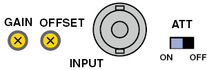
■ Names and functions of the parts of the analog interface board
|
Name |
Description |
|
INPUT |
BNC terminal for applying the external signal Input terminals is electrically isolated from the output terminals of the PCR-M. |
|
ATT |
Input attenuator switch |
|
GAIN |
Variable resistor for fine adjusting the gain (voltage amplification ratio) |
|
OFFSET |
Variable resistor for fine adjusting the offset |
"Varying the voltage of the output AC waveform using DC signals (EXT-AC mode)"
"Amplifying the input waveform (EXT-DC mode)"
The PCR-M outputs AC voltage ranging from 0 V to 135 V (when 135 V range is selected) or 0 V to 270 V (when 270 V range is selected) with respect to a DC signal input ranging from 0 V to ±10 V.
 CAUTION
You have to set the ATT switch to ON. Otherwise the load can be damaged because of PCR500M output an excessive voltage to it.
|
1 |
Check that the POWER switch is turned off. |
|
2 |
Turn the ATT switch on. The allowable input DC voltage range is -10 V to +10 V. |
|
3 |
Connect an external signal (generator) to the INPUT terminal. |
|
4 |
Turn the POWER switch on. |
|
5 |
Press the AC/DC/EXT key (SHIFT+V) to set the OUTPUT mode to EXT-AC. The EXT and AC LEDs illuminate. |
|
6 |
Press the RANGE key (SHIFT+I) to set the voltage range (135 V or 270 V). The LED corresponding to the voltage range illuminates. AUTO cannot be selected. |
|
7 |
Press the F key to set the frequency (40 Hz to 500 Hz). |
|
8 |
Apply an external signal to the INPUT terminal. |
|
9 |
Turn the OUTPUT on. |
■ Setting the limit value
You can set the frequency limit (40 Hz to 500 Hz), the current limit, and the current limit operation (TRIP or LIMIT CONTROL).
|
|
PCR500M |
PCR1000M |
PCR2000M |
PCR4000M |
|
Limit value |
0.1 A to 5.25 A |
0.2 A to 10.5 A |
0.4 A to 21.0 A |
0.8 A to 42.0 A |
■ Fine adjusting the offset
You can fine adjust the offset by turning the OFFSET variable resistor using the adjustment screwdriver. Adjust the offset so that the output voltage is minimum with the input terminal shorted.
■ Fine adjusting the gain
You can fine adjust the gain by turning the GAIN variable resistor using the adjustment screwdriver. Adjust the gain so that the output voltage is 135 Vac (135 V range) when 10 Vdc is applied to the input terminal.
■ Measured value display
The lower numeric display shows RMS, PEAK, and W in order each time the I key is pressed.
The upper numeric display shows the measured RMS voltage.
The input waveform is simply amplified and output in this mode.
• Turn ATT off
Peak value: The PCR-M outputs a voltage 100 or 200 times the voltage ranging from -1.90 V to +1.90 V.
• Turn ATT on
The PCR-M outputs voltage ranging from -190 V to +190 V (when 135 V range is selected) or -380 V to +380 V (when 270 V range is selected) with respect to a signal input ranging from -10 V to +10 V.
|
1 |
Check that the POWER switch is turned off. |
|
2 |
Set the ATT switch. Off: The input voltage range is -1.90 V to +1.90 V (peak value) On: The input voltage range is -10 V to +10 V. |
|
3 |
Connect an external signal (generator) to the INPUT terminal. |
|
4 |
Turn the POWER switch on. |
|
5 |
Press the AC/DC/EXT key (SHIFT+V) to set the OUTPUT mode to EXT-DC. The EXT and DC LEDs illuminate. |
|
6 |
Press the RANGE key (SHIFT+I) to set the voltage range (135 V or 270 V). The LED corresponding to the voltage range illuminates. AUTO cannot be selected. |
|
7 |
If an AC voltage is being applied, press the F key to set the frequency (40 Hz to 500 Hz). To display the measured value accurately, set the frequency so that it matches the frequency of the external input signal. If the set frequency is out of synchronization, the measured value will be unstable. |
|
8 |
Apply an external signal to the INPUT terminal. |
|
9 |
Turn the OUTPUT on. |
■ Setting limit values
You can set the frequency limit (40 Hz to 500 Hz), the current limit (0.1 A to 4.2 A), and the current limit operation (TRIP or LIMIT CONTROL).
|
|
PCR500M |
PCR1000M |
PCR2000M |
PCR4000M |
|
Limit value |
0.1 A to 4.2 A |
0.2 A to 8.4 A |
0.4 A to 16.8 A |
0.8 A to 33.6 A |
■ Fine adjusting the offset
You can fine adjust the offset by turning the OFFSET variable resistor using the adjustment screwdriver. Adjust the offset so that the output voltage is as close to 0 V (DC) as possible with the ATT switch turned off and the input terminal shorted.
■ Fine adjusting the gain
You can fine adjust the gain by turning the GAIN variable resistor using the adjustment screwdriver. Adjust the gain so that the output voltage is 135 Vac (135 V range) when 1.35 Vac is applied to the input terminal with the ATT switch turned off.
■ Measured value display
The lower numeric display shows RMS, PEAK, AVG, and W in order each time the I key is pressed.
The upper numeric display shows the average measured voltage if AVG is selected on the lower numeric display. Otherwise, the upper numeric display shows the measured RMS voltage.
![]() AC power supply PCR-M series
AC power supply PCR-M series
Operation