AC power supply PCR-M series
Operation
The operating conditions are specified.
|
1 |
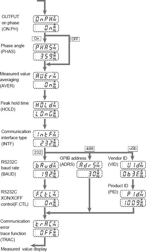
Press the CONFIG key. The configuration setting display appears. The configuration setting switches in order each time the CONFIG key is pressed. Press the CONFIG key repeatedly until the operating condition you wish to set is displayed. The measured value display is shown after all configuration settings are shown. |
|
2 |
Turn the rotary knob to set the condition. |
|
3 |
To set other operating conditions, press the CONFIG key. To show another setting display or the measured value display, press the V, F, or I key. The voltage setting display, frequency setting display, or measured value display is shown, respectively. If you change the communication interface type or change the RS232C settings, you must wait at least 5 seconds, turn the POWER switch off, and then turn it back on. |
"Hold time of peak current""Communication interface"
"Error display during remote control"
Set the OUTPUT on phase for AC mode.
When using the OUTPUT on phase control, also set the phase angle.
• OUTPUT on phase
|
ON ( |
OUTPUT on phase control enabled |
|
OFF ( |
FREE operation (no phase control) |


0 deg to 359 deg : Range for phase angle setting
You can select the averaging period of the measured values (excluding the peak current).
|
ON ( |
Displays the moving average over approximately 3 seconds |
|
OFF ( |
Updates and displays approximately every 0.3 s |


You can change the hold time of the peak current.
• Peak hold time
|
SHORT ( |
Updates approximately every 0.3 s |
|
LONG ( |
Holds the peak value for approximately 5 seconds If a greater peak value is measured while holding, the new peak value is held for approximately 5 seconds from that point. |


The functions of the PCR-M can be expanded by installing an interface board to the option slot. However, the GPIB, RS232C, and USB interfaces cannot be used simultaneously.
• Communication interface type
To activate the settings, the POWER switch must be turned off when at least 5 seconds elapses after changing the settings and then turned back on.
|
232 ( |
RS232C (standard equipped) |
|
488 ( |
GPIB (selectable only when the optional interface board is installed) |
|
USB ( |
USB (selectable only when the optional interface board is installed) |


RS232C
If you select RS232C, set the baud rate and the XON/XOFF flow control.
To activate the settings, the POWER switch must be turned off when at least 5 seconds elapses after changing the settings and then turned back on.
|
1.2/2.4 ... 19.2 : |
1200 bps, 2400 bps, 4800 bps, |
|
ON ( |
XON/XOFF ontrol |
|
OFF ( |
XON/XOFF control |


GPIB
If you select GPIB, select the GPIB address. The dipswitches mounted on the IB21 are not used.
1 to 30 : Address
USB
If you select USB, an ID that is required is displayed. You cannot change the settings.

|
0x1009 ( |
PCR500M |
|
0x100A ( |
PCR1000M |
|
0x100B ( |
PCR2000M |
|
0x1043 ( |
PCR4000M |


■ Error display during remote control
Select whether to show or hide the error number on the lower numeric display when there is an error log in the SCPI error queue during remote control.
• Communication error trace function
|
ON ( |
Show the error number |
|
OFF ( |
Hide the error number |


![]() AC power supply PCR-M series
AC power supply PCR-M series
Operation