AC power supply PCR-M series
Operation
The PCR-M is equipped with the protection functions below. When a protection function is activated, an alarm (A-xx) or an error (E-xx) occurs as shown Table below in and the OUTPUT is turned off.
• Alarm
Occurs to notify the user that a protection function has been activated.
• Error
Occurs on a major operation error or when there is a possibility of malfunction or damage.
|
Protection Function |
Alarm or Error Type |
|
|
Protection against exceeding the input voltage rating range |
Error E-10 or E-12 |
|
|
Overheat protection (OHP) |
Alarm A-04 |
|
|
Overload protection |
Overcurrent (RMS or AVE) protection (OCP) |
OVERLOAD illuminates. Alarm A-01. |
|
Overpower protection (OPP) |
OVERLOAD illuminates. Alarm A-03. |
|
|
Overcurrent (PEAK) protection (OCP) |
OVERLOAD illuminates. Alarm A-02. |
|
|
Voltage error detection |
Overvoltage (OVP) |
Alarm A-00 |
|
Low voltage (LVP) |
Alarm A-06 |
|
"Operation when the protection function is activated"
"Steps to be taken if the circuit breaker trips (PCR2000M/ PCR4000M only)"
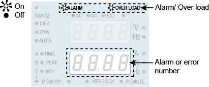
When an alarm or error occurs, an alarm sounds and the ALARM LED on the display illuminates. The upper numeric display shows the output voltage, and the lower numeric display shows the alarm or error number.
|
1 |
Check the alarm number. |
|
2 |
Press the ALM CLR (SHIFT+LIMIT) key. The alarm sound stops, and the alarm indication also clears. If you press the ALM CLR (SHIFT+LIMIT) key again, the last alarm number is displayed. |
|
3 |
Eliminate the cause of the alarm. Eliminate the cause of the alarm that occurred according to the description of the displayed alarm number. |
|
1 |
Check the error number. |
|
2 |
Turn the POWER switch off. |
|
3 |
Eliminate the cause of the error. Eliminate the cause of the error that occurred according to the description of the displayed error number. Turn the POWER switch on again to restore. |
■ Alarm or error number, description, and remedy
|
Alarm Number or Error Number |
Description and Remedy |
|
|
nOEr |
No alarm or error |
|
|
Alarm |
A-00 |
Detected more than 8 V of measured voltage against the setting voltage (OVP, Current limit function: TRIP) or the external signal which exceeds maximum value of the range is applied. |
|
A-01 |
The overload protection function (overcurrent (RMS or AVE) protection) tripped (OCP). |
|
|
A-02 |
The overload protection function (overcurrent (PEAK) protection) tripped (OCP). |
|
|
A-03 |
Power protection function tripped (OPP). |
|
|
A-04 |
The overheat protection function tripped (OHP). The internal temperature may be abnormally high. If the alarm continues to occur after 10 minutes with the POWER switch turned on, it may be caused by an inappropriate installation of the PCR-M or the ambient temperature being outside the operating temperature specifications. |
|
|
A-06 |
Detected less than 8 V of measured voltage against the setting voltage (LVP, Current limit function: TRIP). |
|
|
Error |
E-09 |
An error is occurring in the internal communication. Turn the POWER switch off, wait at least 5 seconds, and then turn the POWER switch back on. |
|
E-10 |
The input voltage is outside the rated range when the power is turned on. Check the input voltage. |
|
|
E-11 |
A voltage error occurred in the internal power unit. Turn the POWER switch off, wait at least 5 seconds, and then turn the POWER switch back on. |
|
|
E-12 |
While the operation, the error has been occurred either the input voltage becomes out of the rated range or the abnormal state is detected in the input circuit. Check the input voltage. Turn off the POWER switch and wait for more than 5 seconds, then turn on the POWER switch again. |
|
|
E-13 |
An error occurred inside the PCR-M. Turn the POWER switch off. Wait at least 5 seconds, and then turn the POWER switch on while holding down the RECALL key. The PCR-M is reset to factory default settings. |
|
|
E-15 |
An error occurred in the calibration data. The error cannot be cleared. Contact your Kikusui agent or distributor for repairs. |
|
- Note -
If you cannot clear the alarm even when all of the causes of the alarm are eliminated, the PCR-M may have malfunctioned. Stop using the PCR-M and contact your Kikusui agent or distributor. When making an inquiry, please provide us with the displayed alarm or error number.
Operation when the protection function is activated
The OVER LOAD LED on the display illuminates for conditions listed in Table below.
The output voltage may vary while the OVER LOAD LED is illuminated.
|
OVER LOAD LED is illuminated |
Operation after an alarm occured |
|
The measured current (RMS) is greater than or equal to the current limit value or rated current. |
Current limit operation : TRIP If this condition lasts for 3 seconds or longer, an alarm (A-01) occurs and the output is shut down. Current limit operation : LIMIT CONTROL (software CC operation) The preset voltage is controlled internally by the PCR-M when an overcurrent condition occurs. An alarm does not occur. |
|
The measured current (PEAK) is greater than or equal to the maximum peak current |
If the condition "100 % of the maximum peak current < measured current ð 115 % of the maximum peak current" lasts for 10 seconds or longer or the condition "115 % of the maximum peak current < measured current" lasts for 1 second or longer, an alarm (A-03) occurs and the output is shut down. |
|
The measured apparent power (VA) is greater than or equal to the rated apparent power. |
If this condition lasts for 10 seconds, an alarm (A-03) occurs and the output is shut down. |
|
The measured voltage (RMS) is not within ±8 V of the preset voltage. |
Current limit operation : TRIP If this condition lasts for 3 seconds, an alarm (A-00 or A-06) occurs and the output is shut down. Current limit operation : LIMIT CONTROL (software CC operation) An alarm does not occur. |
|
The external input signal exceeds the maximum of the range. |
Steps to be taken if the circuit breaker trips (PCR2000M/ PCR4000M only)
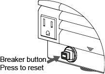
For the PCR2000M/ PCR4000M, if more than 10 A of output current flows from the OUTPUT outlet, the circuit breaker may trip to shut down the output from the OUTPUT outlet. Once the breaker is tripped, the red button (Breaker button) on the front panel will be come out.
|
1 |
Turn the POWER switch off. |
|
2 |
Push the breaker button. |
|
3 |
Adjust the load so that the output current is 10 A or less. |
|
4 |
Turn the POWER switch on. |
![]() AC power supply PCR-M series
AC power supply PCR-M series
Operation