AC power supply PCR-M series
Appendix
Rack mount Frame/ Rack mount bracket
The functions below are expanded depending on the interface board that is installed in the PCR-M.
Selection of AC+DC mode in which DC power is superimposed on the AC power
Increased number of memory sets from 3 to 10.
This is an interface board used to control the PCR-M with the GPIB.
This is an interface board used to control the PCR-M with the USB.
• Analog interface board (EX04-PCR-M)
This is an interface board used to control the output with external analog signals. The following functions are expanded.
The voltage of the output AC waveform (sine wave) is varied according to the input DC signal (EXT-AC mode).
The input waveform is simplify amplified and output (EXT-DC mode).
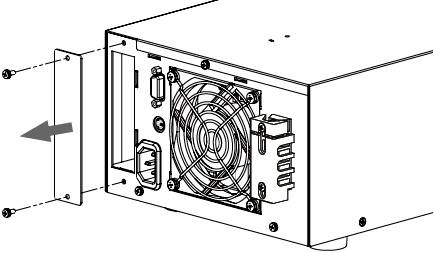
■ Attachment of the Optional Interface Board
Install an interface board to the option slot on the rear panel if you wish to control the PCR-M.
|
1 |
Check that the POWER switch is turned off. |
|
2 |
Touch the grounded metal to discharge your physical static electricity. |
|
3 |
Unfasten the screws that are holding the slot cover in place, and remove the cover from the panel.
|
|
4 |
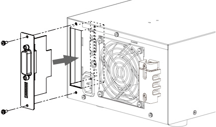
Hold the panel section of the board so that the component side of the printed circuit board is facing right. |
|
5 |
Slide the board into the slot so that the connector section of the printed circuit board is inserted into the connector at the back of the slot.
|
|
6 |
Push the board all the way in |
|
7 |
Use the screws that were holding the slot cover in place to fix the board to the panel. |
|
|
Flame/Bracket model |
Description |
|
PCR500M |
KRA3 |
EIA inch rack |
|
KRA150 |
JIS millimeter rack |
|
|
KBP3-2 |
Blank panel |
|
|
PCR1000M PCR2000M |
KRB3-TOS |
EIA inch rack |
|
KRB150-TOS |
JIS millimeter rack |
|
|
PCR4000M |
KRB6 |
EIA inch rack |
|
KRB300 |
JIS millimeter rack |
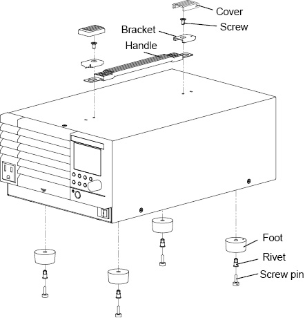
■ Detaching the feet and handle
We recommend that you keep all pieces that you have removed from the PCR-M Series. You will need these pieces if you remove the PCR-M Series from the rack.
PCR500M
|
1 |
Pull up on the handle cover (two locations). |
|
2 |
Unfasten the screws (two locations) and remove the entire handle. |
|
3 |
While pulling down on each foot on the bottom (four locations), turn the screw pin, and remove the foot. Remove all four feet. |
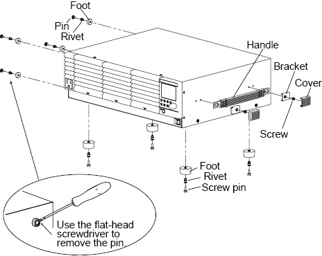
PCR1000M/ PCR2000M
|
1 |
Pull up on the handle cover (two locations). |
|
2 |
Unfasten the screws (two locations) and remove the entire handle. |
|
3 |
While pulling down on each foot on the bottom (four locations), turn the screw pin, and remove the foot. Remove all four feet. |
|
4 |
Unlatch the pin in the foot on the side (four locations) using a flat-head screwdriver, and remove the foot. Remove all four feet. (PCR1000M / PCR2000M only) |
PCR4000M
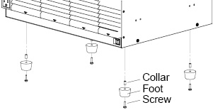
Remove the screw that hold each foot in place to detach the four feet.
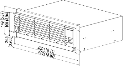
■ Outline diagram and dimensions
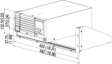
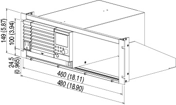
PCR500M
When mounting on an inch rack (frame model KRA3)
When mounting on a millimeter rack (frame model KRA150)
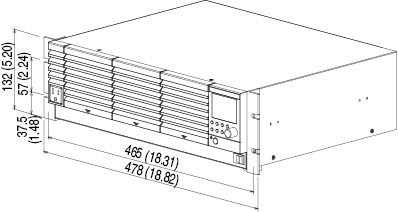
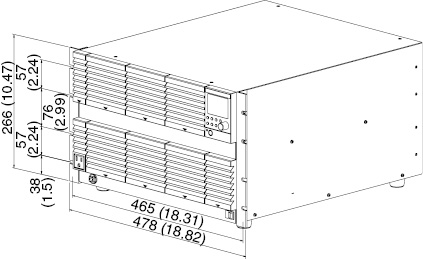
PCR1000M/ PCR2000M
When mounting on an inch rack (bracket model KRB3-TOS)
When mounting on a millimeter rack (bracket model KRB150-TOS)
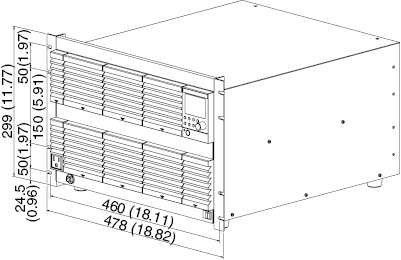
PCR4000M
When mounting on an inch rack (bracket model KRB6)
When mounting on a millimeter rack (bracket model KRB300)
![]() AC power supply PCR-M series
AC power supply PCR-M series
Appendix