AC power supply PCR-M series
Installation and Preparation
The maximum current that the PCR-M Series can generate varies depending on the model. It also varies depending on the PCR-M Series’ output mode, load type, and status. Ensure that the output power capacity is sufficient for the load capacity. The maximum output currents (in AC mode - AC rms, with an output voltage of 1 V to 100 V or 2 V to 200 V, and with a load power factor of 0.8 to 1) for the different models are shown in the table.
|
Voltage range |
PCR500M |
PCR1000M |
PCR2000M |
PCR4000M |
|
135V |
5 A |
10 A |
20 A |
40 A |
|
270V |
2.5 A |
5 A |
10 A |
20 A |
"Connecting to the OUTPUT terminal block"
"Connecting to the outlet on the front panel"
Connecting to the OUTPUT terminal block
■ Preparation of Wire
For connecting the load, use the noncombustible type of load wires which must be rated to carry the maximum rated output current.
Requirements for single-core cables used to connect to the load
|
Nominal Cross-Sectional Area[mm2] |
AWG |
(Reference cross-sectional area)[mm2] |
Allowable Current*[A] |
|
0.9 |
18 |
(0.82) |
17 |
|
1.25 |
16 |
(1.31) |
19 |
|
2 |
14 |
(2.08) |
27 |
|
3.5 |
12 |
(3.31) |
37 |
|
5.5 |
10 |
(5.26) |
49 |
|
8 |
8 |
(8.37) |
61 |
|
14 |
6 |
(13.3) |
88 |
*1. Excerpts from Japanese laws related to electrical equipment.
The values vary depending on conditions such as the wire covering (insulator), the wire material (allowable temperature), and whether there are multiple cores in the cable. For cables other than those specified in this table, consult with a qualified engineer.
 WARNING
Risk of electric shock.
• Use load cables whose capacity is adequate for the PCR-M series' rated output current.
• Use load cables with a voltage rating that meets or exceeds the PCR-M series’ isolation voltage (380 Vdc).
• Before you connect cables to the OUTPUT terminal block, be sure to turn the POWER switch off, and then remove the power plug from the outlet or turn off the switchboard.
- Note -
The L and N terminals of the OUTPUT terminal block are isolated from the input power supply. The polarity does not constitute a problem in terms of safety. You can use either L or N to ground the product.
In DC mode and AC+DC mode, N is the reference. When N has a positive polarity, L is positive electric potential. When N has a negative polarity, L is negative electric potential.
When the POWER switch is on, even if the output is off, a dangerous voltage exists between the output terminal (L or N) and the chassis (G-ground). To eliminate the voltage between the output terminal and the chassis, connect N and G of the OUTPUT terminal block.
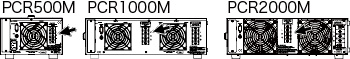
Screw diameter of OUTPUT terminals
PCR500M/ PCR1000M/ PCR2000M : M4
PCR4000M : M6
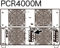
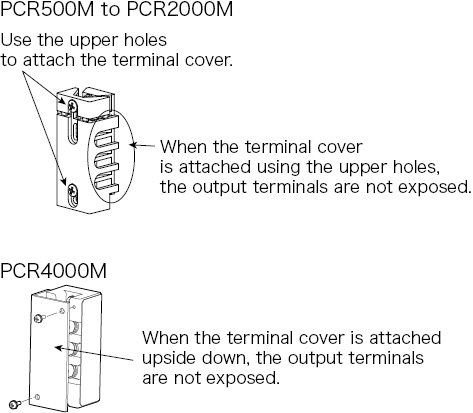
■ Connecting the load cables (PCR500M - PCR4000M)
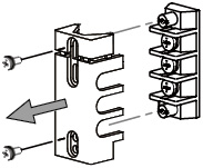
When shipped from the factory, the terminal cover is attached using the upper holes so that the OUTPUT terminals are not exposed.
 WARNING
There is a danger of electric shock. Do not use the terminal block with the terminal cover removed.
|
1 |
Check that the POWER switch is turned off. |
|
2 |
Check that the power cord is disconnected from the outlet or the breaker of the switchboard is off. |
|
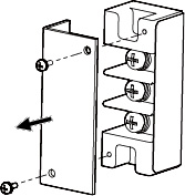
3 |
Remove the terminal cover that is attached to the OUTPUT terminal block.
|
|
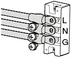
4 |
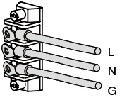
Securely connect the load wires to the OUTPUT terminal block. If the load has a ground (GND) terminal, be sure to connect it to the G terminal of the PCR-M OUTPUT terminal block. Be sure to use a wire that is greater than or equal to the diameter of the wires used to connect the load.
|
|
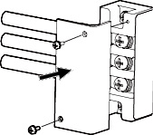
5 |
Attach the terminal cover that you removed in procedure 3 using the lower holes.
|
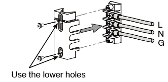
Twist the load wires (L and N), and connect between the output terminal and load with the shortest wires possible. If you cannot twist the wires, we recommend that you run the wires alongside each other and tie them together at several points with cable ties.
■ Connecting the load cables (PCR4000M)
When shipped from the factory, the terminal cover is attached so that the OUTPUT terminals are not exposed.
 WARNING
There is a danger of electric shock. Do not use the terminal block with the terminal cover removed.
|
1 |
Check that the POWER switch is turned off. |
|
2 |
Check that the breaker of the switchboard is off. |
|
3 |
Remove the terminal cover that is attached to the OUTPUT terminal block.
|
|
4 |
Securely connect the load wires to the OUTPUT terminal block. If the load has a ground (GND) terminal, be sure to connect it to the G terminal of the PCR-M OUTPUT terminal block. Be sure to use a wire that is greater than or equal to the diameter of the wires used to connect the load.
|
|
5 |
Attach the terminal cover that you removed in procedure 3.
|
Twist the load wires (L and N), and connect between the output terminal and load with the shortest wires possible. If you cannot twist the wires, we recommend that you run the wires alongside each other and tie them together at several points with cable ties.
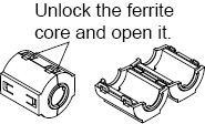
■ Attaching a ferrite core (PCR2000M only).
With the PCR2000M, attach a ferrite core to the wires.
|
1 |
Unlock the ferrite core and open it.
|
|
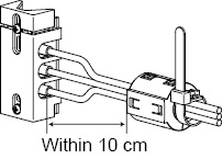
2 |
Close the ferrite core. Avoid catching the wire on the ferrite core. Attach the ferrite core within 10 cm from the OUTPUT terminal block. Lock it securely in place. |
|
3 |
To avoid moving the ferrite core, attach the cable tie to fix the position of the ferrite core.
|
■ When not using the OUTPUT terminal block
If you are not using the OUTPUT terminal block, attach the terminal cover.
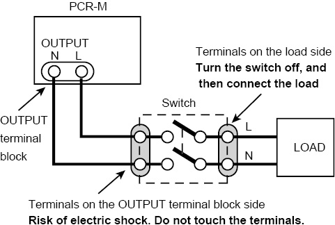
■ When the load is located at a distance from the PCR-M
The remote control enables to turn the output off, but not for the POWER switch off. If the load is used connecting at a distance from the PCR-M, install the switch between the OUTPUT terminal block and the load to prevent electric shock, then turn the switch off.
 WARNING
Possible electric shock
• When installing the switch between the OUTPUT terminal block and the load, be sure to turn the POWER switch off and removing the power plug from an outlet or turn off the circuit breaker of switchboard.
• The current rating of the switch must be greater than or equal to the maximum current of the PCR-M.
• For the switch circuit, use a two-pole type switch that cuts off L and N wires simultaneously.
• Be sure to turn the switch off before connecting the load to the terminal at the load end of the switch.
• Do not touch the switch terminal when the output is on. Do not touch the switch terminals when the POWER switch is on. Before you connect cables to the OUTPUT terminal block, be sure to turn the POWER switch off, and then turn off the switchboard.
The PCR-M can output power from the OUTPUT terminal block on the rear panel and the OUTPUT outlet on the front panel. Specifications are not defined for the OUTPUT outlet. A portion of the performance may be degraded.
 CAUTION
The following table shows the maximum rated voltage and maximum rated current of the outlet on the front panel.
|
|
PCR500M |
PCR1000M |
PCR2000M |
PCR4000M |
|
Maximum rated voltage |
250 Vac(rms) |
|||
|
Maximum rated current |
5 Aac(rms) |
10 Aac(rms) |
||
Do not connect the load when the maximum rated voltage of the OUTPUT outlet is exceeded or when in DC mode, as it can lead to malfunction.
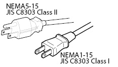
The OUTPUT outlet is dedicated to a type of power plug shown in the figure.
|
1 |
Turn the POWER switch off. |
|
2 |
Connect the power cord of the load device to the OUTPUT outlet. |
![]() AC power supply PCR-M series
AC power supply PCR-M series
Installation and Preparation