AC power supply PCR-LE series
Basic
“Displaying the current, power, and power factor
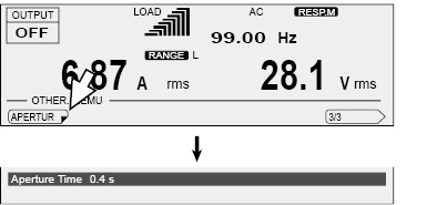
Setting the aperture time (measurement time)
With a longer aperture time, the measurements become more stable, but it takes longer to update the display of the measured values. Guidelines for the aperture time when the signal includes an AC component are given below.
• When the period of the AC is known, you can obtain the most accurate measurement results if you set the aperture time to an integer multiple of the period.
Example: If the period of the AC component is 0.1 s, you can obtain the best results in the shortest time if you set the aperture time to 0.1 s.
• When the period of the AC component is unknown, you can obtain comparatively stable measurement results if you set the aperture time to a value that is at least 10 times the expected period.
If the period is set greater than the aperture time, line voltages cannot be measured correctly.
If the harmonic current analysis function is in use and the period is set greater than the aperture time, correct measurements cannot be made.
Press OTHERS (SHIFT+MEMORY), 1/3 (F6), 2/3 (F6), and then APERTUR (F1) to set the aperture time.
Factory default is 0.4 s.
|
Item |
Title |
Description |
Valid modes |
|
APERTUR |
Aperture Time |
Sets the aperture time (0.1 s to 1.0 s, resolution: 0.001 s). |
All |
The aperture time setting was added in firmware version 5.00. As a result, the function for averaging measured values that was available in firmware version 4.99 and earlier is no longer available.
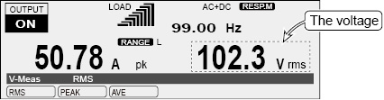
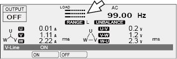
The measured voltage is displayed in the status, measured-value, and setting display area.
The voltage is displayed as an rms value, peak value, or average value.
To switch the display, press V-MEAS (SHIFT+V) to select the item that you want to display.
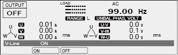
During single-phase, three-wire output and three-phase output (optional), you can select to display phase voltage or line voltage.
|
Item |
Title |
Unit |
Description |
Valid modes |
|
|
RMS |
V-Meas |
V rms |
Displays the rms voltage |
All |
|
|
PEAK |
V pk |
Displays the peak voltage |
|||
|
AVE |
V ave |
Displays the average voltage |
DC and AC+DC |
||
|
LINE*1 |
ON |
V-Line |
V rms |
Displays the line voltage |
AC and DC |
|
OFF |
Displays the phase voltage |
||||
*1. Single-phase three-wire output or three-phase output (optional) only
Line voltage display and Phase voltage display (optional)
|
V-LINE |
OFF (Phase voltage display) |
ON (Line voltage display) |
|
When a single phase is displayed |
|
|
|
When all phases are displayed (single-phase, three-wire output) |
|
|
|
When all phases are displayed (three-phase output) |
|
|


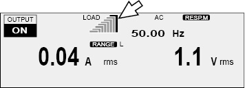
The load level meter displays the ratio of the output current (which is detected as the current flowing through the load) to the rated current on a bar graph. This can be used to determine the approximate output current supply capability. The full scale of the load level meter is 1.1 times the rated current or the current limit, whichever is less.
During single-phase, three-wire output (optional), the load level meter displays the U phase at the top and then the V phase.
During three-wire output (optional), the load level meter displays the U phase at the top followed by the V phase and W phase.
The full scale bar (the right-most bar that lights red) of the load level meter lights on the verge of an overload.
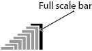
When the PCR-LE is on the verge of an overload, the internal temperature increases. Even if the load is reduced, the full scale bar may continue to light dimly in red. When cooling is complete, the full scale bar turns off.
If overload conditions occur repeatedly while the full scale bar is lit, an alarm (ALM-06: OVERLOAD) may be generated.
Rated current and load level meter display
The output current varies depending on the load. The rated current is automatically derated (reduced) depending on the output conditions (output voltage, frequency, and load power factor).
For details of rated output current, see ”About the output and the load”.
The rated current is automatically derated (reduced) depending on the output conditions (output voltage, frequency, and load power factor).
The following shows an example of how to calculate the rated current on the PCR1000LE.
• If the output voltage is 80 V, the load power factor is 0.6, and the output frequency is 50 Hz,
the rated current is 10 A × 0.825 = 8.25 A.
• If the output voltage is 250 V, the load power factor is 0.4, and the output frequency is 60 Hz,
the rated output current is 1000 W/250 V × 0.65 = 2.6 A.
• If the output voltage is 80 V, the load power factor is 0.6, and the output frequency is 10 Hz,
the rated current is 10 A × 0.775 = 7.75 A (≤ 8.25 A).
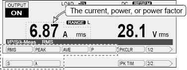
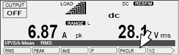
Displaying the current, power, and power factor
The rms current, peak current, average current, power, apparent power, or power factor is displayed in the status, measured-value, and setting display area.
To switch the display, press I/P/S/λ-MEAS (SHIFT+I) to select the item that you want to display.
|
Item |
Title |
Unit |
Description |
Valid modes |
|
RMS |
I/P/S/λ-Meas |
A rms |
Displays the rms current |
All |
|
PEAK |
A pk |
Displays the peak current |
||
|
AVE |
A ave |
Displays the average current |
DC and AC+DC |
|
|
P |
W/kW |
Displays the power |
All |
|
|
S |
VA |
Displays the apparent power |
AC and AC+DC |
|
|
λ |
λ |
Displays the power factor |
||
|
TOTAL P*1 |
W |
Displays the total power |
All |
|
|
TOTAL S*1 |
VA |
Displays the total apparent power |
AC and AC+DC |
|
|
TOTAL λ*1 |
λ |
Displays the total power factor |
*1. Single-phase three-wire output or three-phase output (optional) only
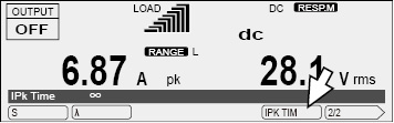
The peak current measurement is displayed as an absolute value of the maximum instantaneous current measured. In DC mode, even if you are generating negative voltage, the peak measured current is displayed as a positive value.
If you have selected the peak current measurement as the measured value that is displayed, you can hold the peak current measurement.
Press I/P/S/l-MEAS (SHIFT+I), 1/2 (F6), and then IPK TIM (F5) to set the hold time.
|
Item |
Title |
Description |
Valid modes |
|
IPK TIM |
IPk Time |
Sets the hold time (0 s to 10 s or ∞). If you use the numeric key pad to specify a value that is greater than or equal to 10, infinity (∞) will be specified. |
All (only when the peak current measurement is being displayed) |
Press I/P/S/l-MEAS (SHIFT+I) and then PKCLR (F5) to clear the peak current.
|
Item |
Description |
|
PKCLR |
Clears the peak current |
![]() AC power supply PCR-LE series
AC power supply PCR-LE series
Basic