AC power supply PCR-LE2 series
Basic
“Explanation of function keys in this manual
“Switching from remote mode to local mode
“Displaying single-phase, three-wire output and three-phase output
“Adjusting the screen brightness
“Locking panel operations (key lock)
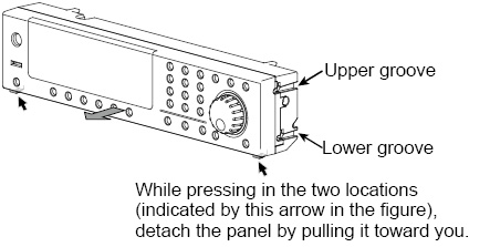
Detaching the control panel
Hold down the two control panel detachment buttons, and pull the control panel toward you.
The control panel will come free of the PCR-LE2 Series. The control panel and the PCR-LE2 Series are connected by a cable. Do not pull hard on the control panel.
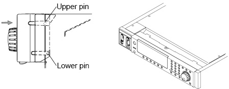
Attaching the control panel
The control panel detachment buttons are not used when you attach the control panel to the PCR-LE2 Series. Simply press on the control panel until you hear a click.
• Factory default
Align the upper groove and the lower groove on the control panel with the upper pin and lower pin on the PCR-LE2 Series, respectively, and then push the control panel back into the PCR-LE2 Series.
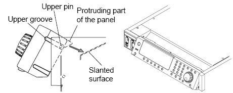
• Tilt slightly
Align the upper groove on the control panel with the upper pin on the PCR-LE2 Series, and then push the control panel back into the PCR-LE2 Series until the protruding part of the control panel lines up with the slanted surface of the PCR-LE2 Series.
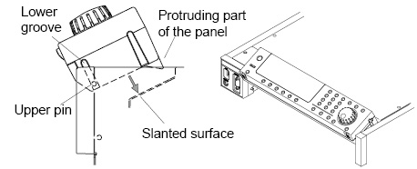
• Make it easily viewable from above.
Align the lower groove on the control panel with the upper pin on the PCR-LE2 Series, and then push the control panel back into the PCR-LE2 Series until the protruding part of the control panel sits on the slanted surface of the PCR-LE2 Series.
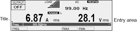
The screen consists of the following three parts.
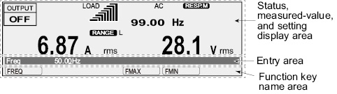
Status, measured-value, and setting display area
This displays the product’s present status, measured values, and settings.
Entry area
Settings and system settings are entered in this area.
This area displays a title and its corresponding setting.
If an alarm or trouble occurs, the alarm code or the trouble code is displayed here.
Function key name area
The present functions are displayed above the function keys (F1 to F6). The displayed contents vary depending on the selected output voltage mode.
|
|
This indicates that you can set the displayed item by pressing the function key. |
|
|
This indicates that there is a sub level in the function menu hierarchy. |
|
|
This indicates that there is another page in the function menu. The function key name indicates the following: “present page/total number of pages.” The PCR-LE2 Series switches between the pages each time that you press this function key. |


Explanation of function keys in this manual
The function keys in this manual are explained in a tabular form as shown below.
|
Item |
Title |
Description |
Conditions in which the function key cannot be used |
Valid modes |
|
The item name that is displayed in the function key name area |
The title that is displayed in the entry area |
An explanation of the function key |
When the PCR-LE2 Series is being used under the conditions listed here, the contents that are listed for the item cannot be selected. |
This indicates the PCR-LE2 Series modes during which the function key is valid. If the valid modes are not listed, the function key is valid in all modes. |
The screen that is displayed that you turn the POWER switch on is called the “home position” (the basic screen). The home position is the top level in the menu hierarchy. All functions are arranged within the menu hierarchy. The home position screen varies depending on the output mode. The figure above is an example for the single-phase output mode.
No matter which function you are using, if you repeatedly press ESC, you will move back up through the menu hierarchy towards the home position.
Press ESC to return to the previous screen.
If you want to cancel settings that you have made, repeatedly press ESC until you return to the home position. If you press ESC at the home position, a buzzer will sound.
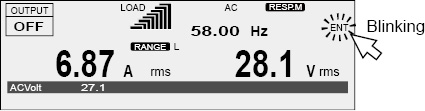
The PCR-LE2 Series has an “ENT wait” state during which you can confirm the operation results (the ENT indicator blinks). The ENT wait state continues until the ENT key is pressed. Press ENT to apply the settings.
Press ESC to cancel the settings.
Restoring to factory default settings
You can return all the settings to their factory defaults or return just a portion of the settings to their factory defaults. For details, see Appendex.A Restoring to factory default settings.
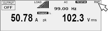
Switching from remote mode to local mode
When the PCR-LE2 Series is in remote mode, “RMT” is displayed on the screen. To switch the PCR-LE2 Series to local mode from the panel, press LOCAL (SHIFT+2).
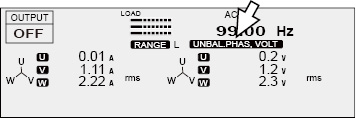
Displaying single-phase, three-wire output and three-phase output
With an unbalanced configuration, the unbalance icon is displayed.
|
Output |
Voltage of each phase |
Phase differences |
Display |
|
|
U and V |
U and W |
|||
|
Single-phase three-wire |
Same |
Other than 180° |
-- |
UNBAL.PHAS |
|
Different |
180° |
-- |
UNBAL.VOLT |
|
|
Different |
Other than 180° |
-- |
UNBAL.PHAS, VOLT |
|
|
Three-phase |
Same |
Other than 120° |
Other than 240° |
UNBAL.PHAS*1 |
|
Different |
120° |
240° |
UNBAL.VOLT |
|
|
Different |
Other than 120° |
Other than 240° |
UNBAL.PHAS, VOLT*1 |
|
*1. If either the “U and V” or “U and W” condition applies, the configuration is considered unbalanced.
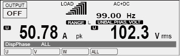
Only one phase can be displayed. Select the phase that you want to display using the PHASE (SHIFT+F) key.
|
Item |
Title |
Description |
|
U |
DispPhase |
The U phase is displayed. The line voltage is the voltage between U and V. |
|
V |
The V phase is displayed. The line voltage is the voltage between V and W. |
|
|
W*1 |
The W phase is displayed. The line voltage is the voltage between W and U. |
|
|
ALL |
All phases are displayed. |
*1. Three-phase output only
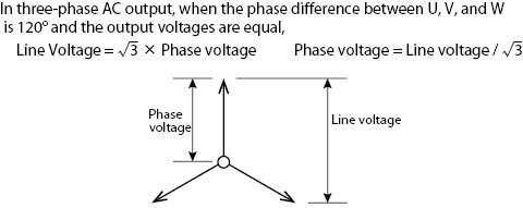
You can display the line voltage.
- Note -
Phase voltage and line voltage
To specify values, use the numeric keypad or the rotary knob. When the cursor is displayed in the entry area, you can use the numeric keypad or the rotary knob to specify a value.
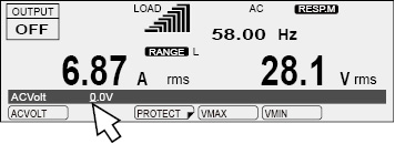
Numeric keypad operations
If you use the numeric keypad to enter a value, the value that you entered is displayed in the entry area.
To enter a negative value, first press +/- (SHIFT+0).
Press CLR to clear any settings that you have made before pressing ENT.
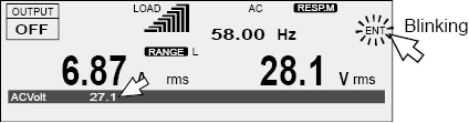
Press ENT to apply the values that you have specified. If you press ESC before you press ENT, any settings that you have made will be canceled.
Turn the rotary knob to the right to increase the displayed value. Turn the rotary knob to the left to decrease the displayed value. You do not need to press ENT.
 CAUTION
A voltage or frequency that is greater than is necessary may cause damage to the load or put the operator in danger. Be sure to set the voltage and frequency limits. For details, see “Setting Limits”.
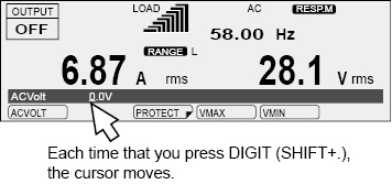
Digit function
The digit function enables you to use the rotary knob to change only the specified digit and the higher digits when you are setting the voltage or frequency. This function is useful when you are changing the voltage or frequency in steps.
|
1 |
Check that the PCR-LE2 Series is in a state in which you can specify a value. The digit function is valid when the cursor is displayed at a value in the entry area. |
|
2 |
Press DIGIT (SHIFT+.) until the cursor is displayed at the digit that you want to change. Only the digit that is indicated by the cursor and the higher digits will be changed (except when the value that you are changing reaches the maximum or minimum settable value). Each time that you press DIGIT (SHIFT+.), the cursor moves to the left. If the cursor is at the highest digit and you press DIGIT (SHIFT+.), the cursor will move to the lowest digit. |
|
3 |
Use the rotary knob to set the value. The digit function is not valid if you are using the numeric keypad to enter the value. |
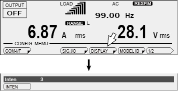
Adjusting the screen brightness
You can set the screen brightness to one of three levels (1 to 3). The larger the number, the brighter the screen.
Press CONFIG (SHIFT+OPR MODE) and then DISPLAY (F4) to set the screen brightness.
|
Item |
Title |
Description |
|
INTEN |
Inten |
Sets the screen brightness |
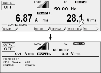
To view the PCR-LE2’s firmware version, press CONFIG (SHIFT+OPR MODE) and then MODEL ID (F5).
Locking panel operations (key lock)
You can lock the PCR-LE2’s keys to prevent mistaken operations such as changes to the settings and overwriting of memory entries.
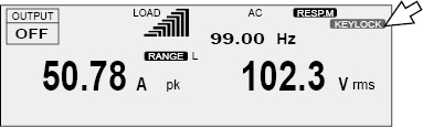
• Locking keys
Press KEYLOCK (SHIFT+5) to lock the panel keys except the OUTPUT key and the KEYLOCK (SHIFT+F5) key. When the keys are locked, “KEYLOCK” is displayed on the screen.
• Unlocking keys
While the keys are locked, press KEYLOCK (SHIFT+5) again to unlock the keys.
![]() AC power supply PCR-LE2 series
AC power supply PCR-LE2 series
Basic