AC power supply PCR-LE2 series
Appendix
Switching steps at specific phase angles
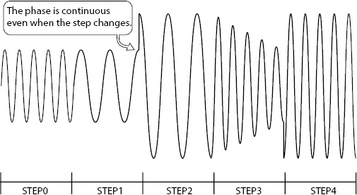
This page explains how to switch steps at specific phase angles to produce a continuous waveform.
Steps are managed in terms of time. If the starting phase angle and ending phase angle are set to FREE (default setting), the next step will start when the step time elapses. The phase is continuous.
|
STEP |
0 |
1 |
2 |
3 |
4 |
|
ACVOLT [V] AC voltage |
5.0 |
5.0 |
10.0 |
5.0 |
10.0 |
|
RAMP (ACVOLT) Voltage ramp |
OFF |
OFF |
OFF |
ON |
OFF |
|
FREQ [Hz] Frequency |
50.0 |
25.0 |
25.0 |
50.0 |
50.0 |
|
TIME [ms] Step time |
100 |
90 |
100 |
100 |
100 |
|
OUTPUT |
ON |
ON |
ON |
ON |
ON |
|
S.PHASE [deg] Starting phase angle |
0 |
FREE |
FREE |
FREE |
FREE |
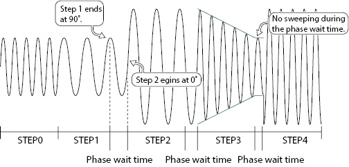
In this example, step 1 ends at 90°, so step 2 begins at 90°. Now, we change the starting phase angle so that steps 2 and 3 begin at 0°, and step 4 begins at 270°.
|
STEP |
0 |
1 |
2 |
3 |
4 |
|
ACVOLT [V] AC voltage |
5.0 |
5.0 |
10.0 |
5.0 |
10.0 |
|
RAMP (ACVOLT) Voltage ramp |
OFF |
OFF |
OFF |
ON |
OFF |
|
FREQ [Hz] Frequency |
50.0 |
25.0 |
25.0 |
50.0 |
50.0 |
|
TIME [ms] Step time |
100 |
90 |
100 |
100 |
100 |
|
S.PHASE [deg] Starting phase angle |
0 |
FREE |
0 |
0 |
270 |
The phase angle of step 1 when its step time elapses is 90°. Because the starting phase angle of step 2 is 0°, the PCR-LE waits until the phase angle of step 1 becomes 0° before executing step 2. This duration is the phase wait time. When the phase angle of step 1 reaches 0°, step 2 begins. The PCR-LE does not sweep during the phase wait time.
If you set starting phase angles, the total sequence time will be longer than the specified time by the amount of phase wait time. The phase wait time depends on the specified frequency.
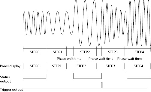
During the phase wait time, the panel shows the next step number.
The status signal is output while the waveform of the step whose STAT.OUT is set to ON is being output.
The trigger signal is produced when the step actually begins.
|
STEP |
0 |
1 |
2 |
3 |
4 |
|
FREQ [Hz] Frequency |
50.0 |
25.0 |
25.0 |
50.0 |
50.0 |
|
S.PHASE [deg] Starting phase angle |
0 |
0 |
0 |
0 |
270 |
|
STAT.OUT Status output |
OFF |
ON |
OFF |
ON |
OFF |
|
TRIG.OUT Trigger output |
OFF |
OFF |
OFF |
ON |
OFF |
You can also set the starting phase angle to FREE and the ending phase angle to a specific angle to product the same effect, but to avoid confusion, we recommend that you set the starting phase angle to a specific angle and the ending angle to FREE.
To output a waveform with continuous phase, be sure to set either the starting or ending phase angle to FREE. If you set both the starting and ending phase angles, the waveform may be offset by one period.
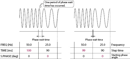
In this example, the starting phase angle of step 1 is FREE, so there is no phase wait time. Theoretically, there should not be any phase wait time if the starting phase angle is set to 0°, but depending on the conditions, the waveform may be offset by on period. If the time and phase angle are matched, we recommend that you use FREE. However, if you want to output an waveform accurately according to calculations, you need to shorten the previous step a little (1 ms in this example).
![]() AC power supply PCR-LE2 series
AC power supply PCR-LE2 series
Appendix