AC power supply PCR-LE2 series
Appendix
Setting Procedure
In the supplied CD-R contains a table for recording sequence operation settings (xls, xlsx, and PDF). You can prevent input errors by entering the settings in this table first and then creating the sequence.
Use the rotary knob or the numeric keypad enter values for items that you want to set. When using the numeric keypad, press ENT after you enter values.
Press SEQ (SHIFT+SIM) to display the sequence screen. Press EDIT (F5) to display the step editing screen.
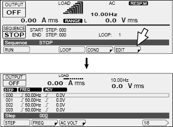
You can edit the step that has a border around its item or value. 000 is selected. If 000 is not selected, use the rotary knob to select it. You can also select steps by pressing STEP (F1) and then using the rotary knob.
Set the AC voltage. Press AC VOLT (F3).
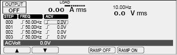
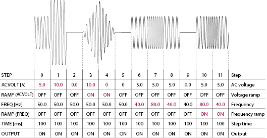
A border is displayed around the ACV item of step 000. Use the rotary knob to specify 5.0 V.
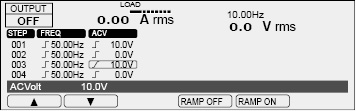
Press ▼ to move the border to the voltage of step 001. Then, use the rotary knob to specify 10.0 V.
The default AC voltage is 0.0 V. The voltage of step 002 is 0.0 V (if it is not, set it to 0.0 V), so press ▼ twice to move the border to the voltage of step 003. In step 3, the voltage changes from 0.0 V to 10.0 V over 100 ms. This is because the voltage ramp setting is on. Use the rotary knob to set the voltage to 10.0 V, and then press RAMP ON (F5). The voltage ramp indication changes to  .
.
In step 4, the voltage changes from 10.0 V to 0.0 V over 100 ms. Set the voltage of step 4 to 0 V, and set the ramp setting to on.
Set the voltages of steps 6 to 8 and steps 10 and 11 to 5.0 V. This completes the voltage settings.
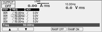
Press ESC to return to the previous screen. Press FREQ (F2) to set the frequency.
The default frequency is 50.0 Hz. Press ▲ repeatedly until you reach the frequency of 006. (If steps 1 to 5 are not set to 50.0 Hz, start by setting the frequencies from step 1.) Then, use the rotary knob to specify 40.0 Hz.
Press ▼ to move the border to the frequency of step 007. Then, use the rotary knob to specify 80.0 Hz. Likewise, set steps 8 and 9 to 40 Hz. Then, press ▼ to move the border to the frequency of step 010.
In step 010, the frequency changes from 40 Hz to 80 Hz over 100 ms. This is because the frequency ramp setting is on. Use the rotary knob to set the frequency to 40 Hz, and then press RAMP ON (F5). The frequency ramp indication changes to  .
.
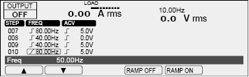
In step 11, the frequency changes from 80 Hz to 40 Hz over 100 ms. Set the frequency of step 11 to 40 Hz, and set the ramp setting to on. This completes the frequency settings.
Press ESC to return to the previous screen. Press 1/5(F6) to move to the next step editing screen.
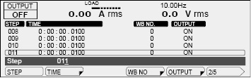
Press TIME (F2) to set the step execution time. Press ▲ repeatedly until you reach the time setting of step 000. Press 100US (F6), use the numeric keys to enter 100 (0:00:00.1000), and press ENT. The microsecond resolution is 100 µs.
The minimum time resolution for the step execution time is 100 µs. Do not set the step execution time to 0 s.
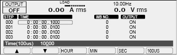
For steps 1 to 11, set the step execution time to 100 ms.
Press ESC to return to the previous screen. The default output setting is on, so there is no need to change it. If it is not on, press OUTPUT (F5). The default settings will be used for the rest of the items. This completes the step settings. If steps 0 to 11 are not set to their default values, set them to default values.
Default values of other items
|
Item |
PCR-LE2 |
Sequence setup screen |
|
DCV (DC voltage) |
0.0 V, RAMP OFF |
3/6 |
|
TYPE (jump type) |
NORM |
4/6 |
|
JUNP STEP (jump destination step) |
0 |
4/6 |
|
JUMP CNT (number of jump repetitions) |
1 |
4/6 |
|
OUT IMP. (output impedance) |
OFF |
5/6 |
|
WB NO (waveform bank number) |
0 |
2/6 |
|
STAT.OUT (status output) |
ON |
3/6 |
|
TRIG.OUT (trigger output) |
OFF |
3/6 |
|
TRIG.IN (trigger input) |
OFF |
3/6 |
|
S.PHASE (starting phase) |
FREE |
5/6 |
|
E.PHASE (ending phase) |
FREE |
5/6 |
|
PHAS.CHG (sudden phase change) |
OFF |
5/6 |
Next, set the sequence conditions.
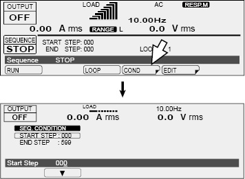
Press ESC repeatedly until the sequence screen appears. Press COND (F4) to set the starting step number and the ending step number.
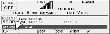
The default starting step number is 0. If START STEP is not 000, use the rotary knob to set it to 000.
Press ▼ to move the border to END STEP. The ending step is 011, so use the rotary knob to specify 011.
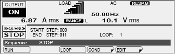
This completes the sequence settings. Let's run the sequence.
Press ESC to display the sequence screen.
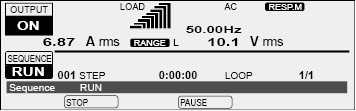
Press RUN (F1) to execute the sequence. You cannot execute the sequence in the following conditions.
If the voltage range is set to the L range and there is a step whose voltage exceeds the output voltage setting range (switch the range to the H range, or set the output voltage so that it is within the L range).
If you have configured the PCR-LE Series so that it does not turn output off when the current limit is exceeded (DISABLE)
If the regulation adjustment or soft sensing compensation function is in use.
If the L range is selected and a step's ACVolt or DCVolt setting is outside of the L range.
If the voltage or frequency is set to a value outside the corresponding limits.
The minimum unit for displaying step execution times is seconds. Steps whose execution time is less than 1 second are displayed as "0:00:00."
A sequence is complete when all steps are complete. The condition that the PCR-LE Series is in when a sequence is completed is the condition specified in the last step of the sequence.
If you want the output to turn off when the sequence is complete, you need to add a last step that turns the output off.
When you have finished setting the sequence, we recommend that you save the settings to a USB memory device.
Connect a USB memory device to the USB port on the front panel. Press OTHERS (SHIFT+MEMORY), 1/2(F6), FILE(F5), SAVE(F3), and SEQ. The name of the file that the sequence will be saved to is displayed in the entry area.
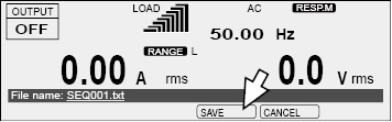
Press SAVE (F4) to save the settings. Do not remove the USB memory device until "File was saved" disappears.
Remove the USB memory device from the USB port.
![]() AC power supply PCR-LE2 series
AC power supply PCR-LE2 series
Appendix