AC power supply PCR-LE2 series
Advanced
Wiring the hard sensing and soft sensing functions
Compensation function setup procedure
Checking the sensing functions (excluding the regulation adjustment function)
 WARNING
Risk of electric shock.
• Before you connect the load or the sensing cables, turn the POWER switch off, and then turn off the switchboard.
• Firmly attach the terminal box cover.
Connect the PCR-LE2’s internal output voltage compensation point directly across the load. Because compensation is performed in real time, the output voltage can be stabilized at a high speed.
Because the impedance (the combination of the resistance and the inductance) of the power line across the load will be included in the compensation circuit, the power circuit’s stability decreases. The PCR-LE2 Series operations may become unstable (for example, it may oscillate) depending on the wiring and the load type. Because the power wires of each phase (L and N) are not paired during single-phase three-wire output or three-phase three-wire output, the operation tends to be more unstable than during single-phase output.If the operations become unstable, use soft sensing.
It is recommended that you use soft sensing if you are using a load that does not require a fast output voltage response speed.
You cannot use hard sensing in the following situations.
When the output is on
When you are setting the output impedance (ON)
When you have selected the normal response speed (MEDIUM).
The voltage of the sensing point is measured by the PCR-LE2 Series measurement functions, and any insufficiencies in the voltage are automatically compensated for. The performance of the PCR-LE2 Series such as the stability of the voltage, output voltage response to sudden changes in the load current, and waveform quality (distortion ratio) is lower than that available during normal operation.
Even in DC mode, the performance is lower than that available during remote sensing of a normal DC power supply.
The maximum voltage that soft sensing can compensate is “the PCR-LE2 Series’ output voltage ±10 %.” The maximum output voltage during compensation is limited by the rated voltage of the PCR-LE2 Series.
If the frequency is less than 40 Hz, soft sensing is disabled.
You cannot use soft sensing in the following situations.
When the output is on
When in AC+DC mode
When you are setting the output impedance (ON)
When you have configured the PCR-LE2 Series so that it does not turn output off when the current limit is exceeded (DISABLE)
When you have specified the waveform bank
When power line abnormality simulations are being performed
When sequences are being performed
When soft start is on.
This function calculates the voltage drops that are caused by the output current and increases the output voltage just by the calculated voltage drops.
Use this function when there is a great distance between the PCR-LE2 Series and the load and you want to stabilize the voltage across the load. This function does not require you to connect the sensing cables that the hard sensing and soft sensing functions require.
The performance of the stabilization accuracy, distortion ratio, and response speed of the voltage is lower than the normal performance of the PCR-LE2 Series. Depending on how you are using the PCR-LE2 Series, you may not be able to use this function. Check the operation that you will perform before you use the regulation adjustment function.
The maximum voltage that regulation adjustment can compensate is “the PCR-LE2 Series’ output voltage + 10 %.” The maximum output voltage during compensation is limited by the rated voltage of the PCR-LE2 Series. If the output current is 10 % or less of the maximum rated current, the voltage is not compensated.
You cannot use regulation adjustment in the following situations.
When the output is on
When in AC+DC mode, in DC mode
When you are setting the output impedance (ON)
When you have configured the PCR-LE2 Series so that it does not turn output off when the current limit is exceeded (DISABLE)
When you have specified the waveform bank
When power line abnormality simulations are being performed
When sequences are being performed
When soft start is on.
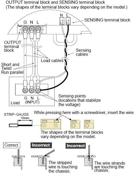
We recommend that you run the load wires alongside each other and tie them together at several points with cable ties. Connect between the output terminal and load with the shortest wires possible.
The sensing feature can compensate up to 1.5 V for a single line. Select a load cable that has sufficient current capacity to prevent the voltage drop in the cable from exceeding the compensation voltage.
As the PCR-LE2 Series output voltage becomes small, so too does the detected voltage. If the PCR-LE2 Series output voltage is small, reduce the voltage drops in the cables by using cables that have large diameters to wire the load, connecting the load so that the cables are as short as possible, and taking other similar precautions.
 CAUTION
Risk of damage to the product and the load. If the sensing cables become disconnected or the polarities are incorrect, an overvoltage will be generated in the output. The protection function will be activated and the output will be turned off, but an overvoltage will be generated for the several hundreds of milliseconds before the protection function is activated.
On the PCR6000LE2 and PCR9000LE2, pull out the terminal block tray, and then connect the sensing cables.
On the PCR12000LE2, PCR18000LE2, and PCR27000LE2, remove the SENSING terminal cover, and then connect the sensing cables.
Use AWG22 to AWG16 cables when connecting to the sensing terminals. Strip approximately 10 mm of coating from the end of the cables.
The following figure illustrates how to connect sensing cables to the PCR6000LE2 for single-phase output.
|
1 |
Check that the POWER switch is turned off. |
|
2 |
Check that the load’s power switch is off. If you cannot turn the load off, install a dedicated terminal block for sensing. Do not connect the load to this dedicated terminal block for sensing. |
|
3 |
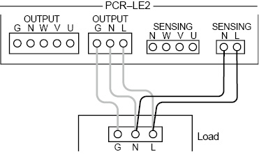
Connect the N SENSING terminal to the N terminal on the DUT using sensing cables. In the same way, connect the L SENSING terminal to the L terminal on the DUT. Connect the wiring so that the product is as close to the load as possible. |
• Single-phase output
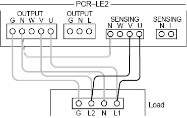
• Single-phase three-wire output
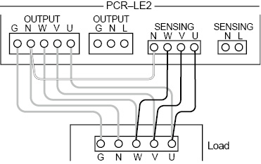
• Three-phase output
Wiring the regulation adjustment function
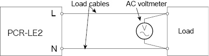
After you finish connecting the load, turn the output on. Then, set the output voltage to the voltage that is required across the load. Because of voltage drops in the load wiring, the voltage across the load is lower than the voltage generated by the PCR-LE2 Series. Use a voltmeter (or other instrument that enables you to measure voltage) to check whether the voltage across the load is the required voltage.
The maximum voltage that regulation adjustment can compensate is “the PCR-LE2 Series’ output voltage + 10 %.”
Set the voltage and the frequency that you want to stabilize at the sensing point. In DC mode, set only the voltage.
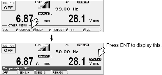
Press OTHER (SHIFT+MEMORY), 1/3 (F6), and then COMPEN (F2) to configure the compensation functions.
|
Item |
Title |
Description |
Conditions in which the function key cannot be used |
Valid modes |
|
OFF |
Compensation |
The compensation (voltage compensation) functions are not used. |
None |
All |
|
SENS.-H |
The hard sensing function is used. |
Output: on Output impedance: setting Response: MEDIUM |
||
|
SENS.-S |
The soft sensing function is used. |
Output: on Output impedance: setting Action to perform when the current limit is exceeded: DISABLE Waveform bank: specified Soft start: on Power supply line error simulation: being performed Sequence: being performed |
AC and DC |
|
|
REG ADJ*1 |
The regulation adjustment function is used. Allow a current to flow through the load. Then, check the voltmeter that is attached across the load, and use the rotary knob to adjust the PCR-LE2 Series voltage to the same value that is displayed. |
AC |
*1. Not valid in single-phase three-wire output and three-phase output
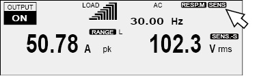
If the frequency is less than 40 Hz, soft sensing is disabled. If the output is on and soft sensing is disabled, “SENS” appears on the screen.
Adjusting the regulation adjustment function
Checking the sensing functions (excluding the regulation adjustment function)
When you are using the hard sensing function or soft sensing function, after you finish wiring the sensing cables, check that there are no wiring errors. Turn the load’s power switch off before you perform this check.
|
1 |
Turn the POWER switch on. |
|
2 |
Set the output undervoltage protection (UVP) to 5 V. |
|
3 |
Set the output overvoltage protection (OVP) to 20 V. |
|
4 |
Set the output voltage range to the H range. |
|
5 |
Set the output voltage to 10 V, and then turn the output on. |
|
6 |
Check whether a voltage of several tens of volts is being generated. An output being generated in this situation indicates that there are connection errors. Check whether the sensing cables are connected and whether the polarities are correct. If the sensing cables are disconnected or the polarities are incorrect, a voltage will be applied across the load (at the sensing point) for approximately one second until the protection function is activated. |
If the sensing cables are not firmly connected, an alarm (ALM-07: UVP or ALM-22: SENSING FAILURE) may be generated. If the polarities of the sensing cables are not correct, an alarm (ALM-00: OVP) may be generated. Connect the cables correctly.
If you are installing a dedicated terminal block for sensing, check the sensing function before you connect the load to the terminal block.
![]() AC power supply PCR-LE2 series
AC power supply PCR-LE2 series
Advanced