AC power supply PCR-LE2 series
Advanced
The synchronization function synchronizes the frequency and phase of the PCR-LE2 Series output voltage with a 50 Hz or 60 Hz input power supply. This is valid in AC mode and AC+DC mode.
This is useful in situations such as when the display of an external measuring instrument is not stable.
Setting the synchronization delay phase angle enables you to manage the synchronization phase of the input voltage on the three-phase input model with a high degree of precision.
Turning the synchronization function on disables the frequency limit function.
Turning the synchronization function on and off
If the input voltage frequency is outside of the rated range or if the input power supply voltage distortion and the noise are extremely large, synchronization is not possible. In these situations, “SYNC NG” is displayed.
Press SYNC (SHIFT+9) to turn the synchronization function on and off.
|
Item |
Title |
Description |
Valid modes |
|
ON |
Sync |
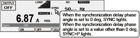
The synchronization function is enabled. “SYNC” or “SYNC+P” blinks until synchronization is established. After a few seconds, the frequency and the phase are synchronized, “SYNC” or “SYNC+P” lights, and the synchronized frequency is displayed. |
AC and AC+DC |
|
OFF |
The synchronization function is disabled. |
Setting the synchronization delay phase angle
Press SYNC (SHIFT+9) and then DELAY (F4) to set the value.
|
Item |
Title |
Description |
Valid modes |
|
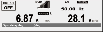
DELAY |
Sync delay deg |
Sets the synchronization delay phase angle (0 deg to 359 deg) |
AC and AC+DC |
The frequency that is used when the synchronization function is cleared
If the frequency when you are using the synchronization function is within the frequency limits, the frequency is set to the 50 Hz or 60 Hz, whichever the PCR-LE2 Series was synchronized to.
If the frequency when you are using the synchronization function is outside the frequency limits, the frequency limit function will be activated.
If the frequency when you are using the synchronization function is lower than the lower limit, the frequency is set to the lower limit.
If the frequency when you are using the synchronization function is higher than the upper limit, the frequency is set to the upper limit.
Phase
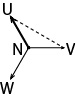
The figure below shows the phase synchronization behavior for different input-wiring and output configurations.
|
Input wiring
|
Single-phase output Single-phase, three-wire output |
Three-phase output |
|
Single-phase input (PCR6000LE2) |
In-phase with the input |
VU-N and VL-N are in phase. |
|
Three-phase, three-wire 200 V input |
In-phase with input VR-S |
VU-N and VR-S are in phase. |
|
Three-phase, four-wire input 400 V input |
In-phase with input VR-N |
In-phase with the input |


![]() AC power supply PCR-LE2 series
AC power supply PCR-LE2 series
Advanced