
PAT80-100T (400 V input) specification
 Open PDF file(92 Kb)
Unless specified otherwise, the specifications are for the following settings and conditions.
- The load is a pure resistance.
- The warm-up time is 30 minutes (with current flowing).
- After warm-up is complete, the PAT-T series must be calibrated correctly according to the procedures given in the operation manual in a 23 °C ± 5 °C environment.
- TYP (typical) values do not guarantee the performance.
- rtg: Indicates the rated output.
- rdng: Indicates the reading.
- Rated load and no load are defined as follows.
During constant voltage operation (set the output current at the rated voltage output greater than equal to the rated output current)- Rated load: Refers to a load with a resistance that makes the current that flows when the rated output voltage is applied to be 95 % to 100 % of the rated output current at the rated output voltage.
- No load: Refers to a load through which no output current flows or an open output terminal condition with no load connected.
During constant current operation (set the output voltage at the rated output current greater than equal to the rated output voltage)- Rated load: Refers to a load with a resistance that makes the voltage drop when the rated output current is supplied to be 95 % to 100 % of the maximum output voltage at the rated output current.
The output voltage of the PAT-T series including the voltage drop in the load cable must not exceed the maximum output voltage at the rated output current. - No load: Refers to a load with a resistance that makes the voltage drop when the rated output current is supplied to be 10 % of the maximum output voltage or 1 V, whichever is greater, at the rated output current.
AC input
| Nominal input rating | 400 V, 50 Hz to 60 Hz, three-phase | |
| Input voltage between U-G, V-G, and W-G *1 | ±254 Vmax | |
| Input voltage range | 360 V to 440 V | |
| Input frequency range | 47 Hz to 63 Hz | |
| Hold-up time for power interruption (MIN) | 20 ms or greater (at 50 % load), 5 ms or greater (at the rated load) |
|
| Current (MAX) *2 | 18 A | |
| Inrush current (MAX) *3 | 40 Apeak | |
| Wattage (MAX) *2 | 10 kVA | |
| Power factor (TYP) *4 | 0.95 | |
| Efficiency (MIN) *4 | 85 % | |
*1. At input terminals of the PAT.
*2. At the rated load.
*3. Excludes the charge current component that flows through the capacitor of the internal EMC filter circuit immediately after the POWER switch is turned on (within approximately 1 ms).
*4. Input voltage of 400 Vac, at the rated load.
Output
| Rating | Output power | 8 kW | |
| Output voltage | 80.00 V | ||
| Output current | 100.0 A | ||
| Voltage | Preset range | 0 % to 105 % of rtg *1 | |
| Setting accuracy | ± (0.2 % of rtg +50 mV) *2 | ||
| Line regulation | ±(0.05 % of rtg + 5 mV) *3 | ||
| Load regulation | ±(0.1 % of rtg + 5 mV) *4 | ||
| Transient response | 5 ms *5 | ||
| Ripple noise | (p-p) | 350 mV *6 | |
| (rms) | 30 mV *7 | ||
| Rise time (MAX) | Rated load | 100 ms *8 | |
| No load | 100 ms *8 | ||
| Fall time (MAX) | Rated load | 100 ms *9 | |
| No load | 2000 ms *9 | ||
| Temperature coefficient (MAX) | 100 ppm/°C (during external control) *10 | ||
| Current | Preset range | 0 % to 105 % of rtg *1 | |
| Setting accuracy | ±(0.5 % of rtg + 50 mA) *2 | ||
| Line regulation | ±(0.1 % of rtg + 30 mA) *3 | ||
| Load regulation | ±(0.2 % of rtg +30 mA) *4 | ||
| Ripple noise (rms) | 300 mA *7 | ||
| Temperature coefficient (TYP) | 200 ppm/°C (during external control) *10 | ||
*1. The maximum preset voltage and current are used to determine constant voltage or constant current operation when the activation point of the constant voltage or constant current operation is set to the rated output voltage or current. It does not guarantee power supply to the load exceeding the rated output voltage or current.
To establish a constant voltage operation at the activation point (rated output voltage or current), set the output current (I Set) so that rated output current < I Set ≤ maximum preset current. Likewise, to establish constant current operation, set the output voltage (V Set) so that rate output voltage < V Set ≤ maximum preset voltage.
*2. The difference between the actual output voltage or output current and the preset value under constant voltage or constant current operation.
*3. Output voltage or output current fluctuation with respect to ±10 % fluctuation of the nominal input voltage under constant voltage or current operation.
*4. Output voltage or output current fluctuation when the output voltage or output current is set to the rated output voltage or current and the load is changed from rated load to no load under constant voltage or current operation.
*5. The time it takes for the output voltage fluctuation to recover from outside 0.1 % + 10 mV of the output voltage setting to within 0.1 % + 10 mV when the output current is changed from 100 % to 50 % or 50 % to 100 % of the rated output current under constant voltage operation. The output voltage when the output current is 100 % is used as a reference. When the remote sensing function is used.
*6. When the measurement frequency bandwidth is 10 Hz to 20 MHz.
*7. Output voltage is 10 % to 100 % of the rating when the measurement frequency bandwidth is 5 Hz to 1 MHz.
*8. The time it takes for the output voltage to rise from 10 % to 90 % of the rating when the output is turned on.
*9. The time it takes for the output voltage to fall from 90 % to 10 % of the rating when the output is turned off.
*10. When the ambient temperature is within the range of 0 °C to 50 °C.
Display function
| Voltmeter | Maximum display | 99.99 (fixed decimal point) | |
| Display accuracy | ± (0.2 % of rdng +5 digits) at 23 °C ± 5 °C | ||
| Ammeter | Maximum display | 999.9 (fixed decimal point) | |
| Display accuracy | ± (0.5 % of rdng +5 digits) at 23 °C ± 5 °C | ||
| Operation display | OUTPUT ON/OFF | ON: OUTPUT LED illuminates (Green LED). OFF: OUTPUT LED turns off. |
|
| ALM operation | ALARM LED illuminates (Red LED). *1 | ||
| CV operation | CV LED illuminates (Green LED). | ||
| CC operation | CC LED illuminates (Red LED). | ||
| RMT operation | RMT LED illuminates during remote control (Green LED). | ||
| EXT operation | EXT LED illuminates during external control (Green LED). | ||
| LOCK operation | LOCK LED illuminates when the keys are locked (Green LED). | ||
*1. Illuminates when the overvoltage protection (OVP), overcurrent protection (OCP), overheat protection (OHP), input open-phase protection (PHASE), fan failure protection (FAN), incorrect sensing connection protection (SENSE), overheat protection of the bleeder circuit (BOHP) and so on are activated.
Illuminates even when the breaker trips (even when the POWER switch is turned off). In this case, the LED illuminates for approximately 10 to 15 seconds.
Protection functions
| Overvoltage protection (OVP) | Turns off the output or trips the breaker (turns the POWER switch off). ALARM LED illuminates.*1 |
|
| Selectable range | 10 % to 111.5 % of the rated output voltage | |
| Setting accuracy | ± 2 % of rtg | |
| Overcurrent protection (OCP) | Turns off the output or trips the breaker (turns the POWER switch off). ALARM LED illuminates.*1 |
|
| Selectable range | 10 % to 111.5 % of the rated output current | |
| Setting accuracy | ± 3 % of rtg | |
| Overheat protection (OHP) | Trips the breaker (turns the POWER switch off). ALARM LED illuminates. | |
| Input open-phase protection (PHASE) | Turns the output off. ALARM LED illuminates. | |
| Fan failure protection (FAN) | Turns the output off. ALARM LED illuminates. | |
| Incorrect sensing connection protection (SENSE) | Turns the output off. ALARM LED illuminates. | |
| Overheat protection of the bleeder circuit (BOHP) | Turns the output off. ALARM LED illuminates. | |
| Shut down (SD) | Turns off the output or trips the breaker (turns the POWER switch off). ALARM LED illuminates.*1 |
|
*1. Illuminates even when the breaker trips (even when the POWER switch is turned off). In this case, the LED illuminates for approximately 10 to 15 seconds.
Output signals
| Monitor signal output*1 | VMON (Voltage) | At rated voltage output | 10.00 V ± 0.25 V |
| At 0 V output | 0.00 V ± 0.25 V | ||
| IMON (Current) | At rated current output | 10.00 V ± 0.25 V | |
| At 0 A output | 0.00 V ± 0.25 V | ||
| Status signal output *1, *2 | OUTON STATUS | Turns on when the output is on. | |
| CV STATUS | Turns on during CV operation. | ||
| CC STATUS | Turns on during CC operation. | ||
| ALM STATUS | Turns on when an alarm (OVP, OCP, OHP, BOHP, input open-phase protection, fan failure protection, incorrect sensing connection protection, or shutdown) is detected. | ||
| PWR OFF STATUS | Stays on for approximately 10 to 15 seconds after the POWER switch turns off. | ||
| PWR ON STATUS | Turns on when the POWER switch is on. | ||
*1. J1 connector on the rear panel.
*2. Photocoupler open collector output, maximum voltage 30 V, maximum current (sink) 8 mA, insulated from the output and control circuits, and status signals are not mutually insulated.
Control functions
| External control*1 | EXT-V CV CONT *2 *3 (CV external voltage control) |
0 % to 100 % of the rated output voltage in the range of 0 V to 10 V. |
| EXT-V (FAST) CV CONT *2 *3 (CV external voltage control FAST) |
0 % to 100 % of the rated output voltage in the range of 0 V to 10 V. | |
| EXT-R CV CONT *2 (CV external resistance control) |
0 % to 100 % of the rated output voltage in the range of 0 kΩ to 10 kΩ. | |
| EXT-R (FAIL SAFE) CV CONT *2 (CV external resistance control FAIL SAFE) |
100 % to 0 % of the rated output voltage in the range of 0 kΩ to 10 kΩ. | |
| EXT-V CC CONT *2 *3 (CC external voltage control) |
0 % to 100 % of the rated output current in the range of 0 V to 10 V. | |
| EXT-V (FAST) CC CONT *2 *3 (CC external voltage control FAST) |
0 % to 100 % of the rated output current in the range of 0 V to 10 V. | |
| EXT-R CC CONT *2 (CC external resistance control) |
0 % to 100 % of the rated output current in the range of 0 kΩ to 10 kΩ. | |
| EXT-R (FAIL SAFE) CC CONT *2 (CC external resistance control FAIL SAFE) |
100 % to 0 % of the rated output current in the range of 0 kΩ to 10 kΩ. | |
| OUTPUT ON/OFF CONT*4 | Output on with a low TTL level signal/output on with a high TTL level signal. | |
| SHUT DOWN*5 | POWER switch off with a low TTL level signal. |
*1. J1 connector on the rear panel.
*2. Set EXT-V, EXT-V (FAST), EXT-R, and EXT-R (FAIL SAFE) in the CONFIG settings. The selected function is enabled.
*3. The input impedance EXT-V CV CONT, EXT-V (FAST) CV CONT and EXT-V CC CONT, EXT-V (FAST) CC CONT is approximately 100 kΩ.
The setting accuracy is ±5 % of the rated output voltage or ±5 % of the maximum output current.
*4. Set the logic low/high using CONFIG settings.
*5. The output turns off even if the breaker trip setting of the CONFIG parameter is set so that the POWER switch does not turn off.
Interface
| Common specifications | Software protocol | IEEE Std 488.2-1992 |
| Command language | Complies with the SCPI Specification 1999.0 specifications. | |
| RS232C | Hardware | Complies with EIA232D. |
| D-SUB 9-pin connector (male) *1 | ||
| Baud rate: 1200, 2400, 4800, 9600, 19200, and 38400 bps | ||
| Data length: 7 bits or 8 bits. Stop bit: 1 bit or 2 bits. No parity. | ||
| Flow control X-Flow or none. | ||
| Program message terminator | LF during reception, CR/LF during transmission. | |
| GPIB*2 | Hardware | Complies with IEEE Std 488.1-1987. |
| SH1, AH1, T6, L4, SR1, RL1, PP0, DC1, DT1, C0, and E1. | ||
| 24 pin connector (receptacle) | ||
| Program message terminator | LF or EOI during reception, LF+EOI during transmission. | |
| Primary address | 1 to 30 | |
| USB*2 | Hardware | Complies with USB 2.0. Data rate: 12 Mbps (full speed). |
| Socket B type | ||
| Program message terminator | LF or EOM during reception, LF+EOM during transmission. | |
| Device class | Complies with the USBTMC-USB488 device class specifications. | |
| LAN*2 | Hardware | IEEE 802.3 100Base-TX/10Base-T Ethernet Complies with the LXI Class C, Specification 1.2. |
| IPv4, RJ-45 connector *3 | ||
| Communications protocol | VXI-11 | |
| Program message terminator | LF or END during reception, LF+END during transmission. |
*1. Use a cross cable (null modem cable).
*2. Factory option.
*3. Category 5, use a straight cable.
Other functions
- Master-Slave parallel operation
- Output status setting at power-on setting
- Output on / off delay setting
- Preset memory
- Lock
- Fine adjustment
- Voltage / current setting limit
- Communication error display
General specifications
| Weight | Approx. 24 kg (52.91 lb) |
|
| Dimensions | See the outline drawing | |
| Environmental conditions | Operating conditions | Indoor use, Overvoltage Category II |
| Operating temperature | 0 °C to +50 °C (32 °F to +122 °F) | |
| Operating humidity | 20 %rh to 85 %rh (no condensation) | |
| Storage temperature | -25 °C to +70 °C (-13 °F to +158 °F) | |
| Storage humidity | 90 %rh or less (no condensation) | |
| Altitude | Up to 2000 m | |
| Cooling system | Forced air cooling using a fan. (With fan control) | |
| Grounding polarity | Negative grounding or positive grounding possible. | |
| Isolation voltage | ± 250 Vmax | |
| Withstand voltage | Across the input terminals and chassis | No abnormalities at 1500 Vac for 5 seconds. |
| Across the input terminals and the output terminals | No abnormalities at 1500 Vac for 5 seconds. | |
| Across the output terminals and chassis | No abnormalities at 500 Vdc for 1 minute. | |
| Insulation resistance | Across the input terminals and chassis | 500 Vdc, 30 MΩ or more. (at 70 %rh or less) |
| Across the input terminals and the output terminals | 500 Vdc, 30 MΩ or more. (at 70 %rh or less) | |
| Across the output terminals and chassis | 500 Vdc, 30 MΩ or more. (at 70 %rh or less) | |
| Safety | Complies with the requirements of the following standard. IEC61010-1:2001 (Class I *1, Pollution degree 2 *2) |
|
| Accessories | Output terminal cover | 2 sets (with screws) |
| Output terminal bolt set | 2 sets (M10 × 20 mm bolts, nuts, and spring washers) | |
| Heavy object warning label | 1 pc. | |
| J1/J2 connector kit | 1 set (2 sets of protection covers, 2 sokets, and 30 pins) | |
| Chassis connection wire | 1 set (with screws) | |
| Quick Reference (base model) | 1 pc. (english), 1 pc. (japanese) | |
| Setup Guide | 1 copy | |
| Safety Information | 1 copy | |
| CD-ROM | 1 pc. | |
*1. This is a Class I sequipment. Be sure to ground the PAT-T series’s protective conductor terminal. The safety of this product is only guaranteed when the product is properly grounded.
*2. Pollution is addition of foreign matter (solid, liquid or gaseous) that may produce a reduction of dielectric strength or surface resistivity. Pollution Degree 2 assumes that only non-conductive pollution will occur except for an occasional temporary conductivity caused by condensation.
Dimensions
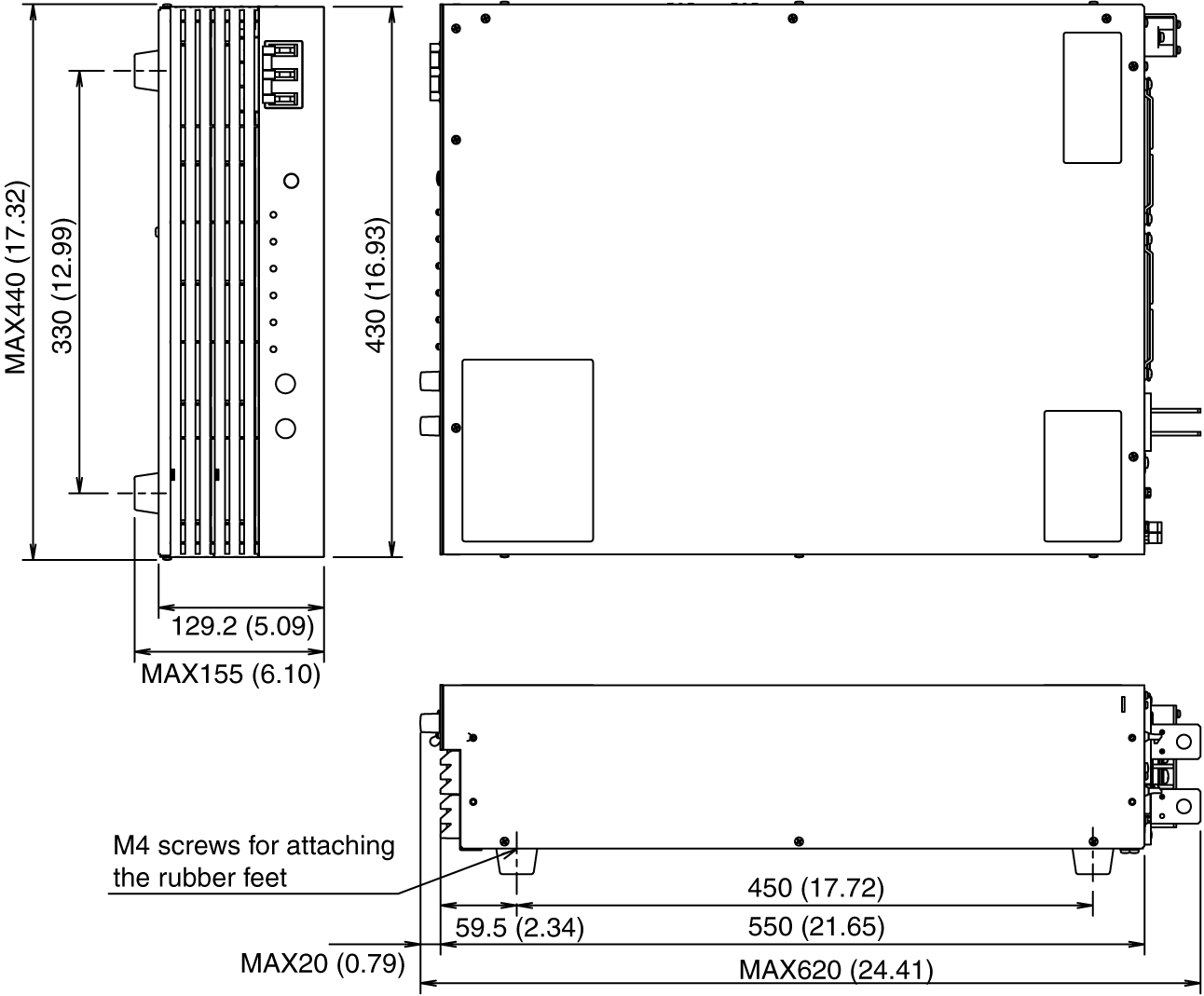
Unit: mm (inch)
PAT-T Series Outline Drawing